| DOCs and SPECIFICATIONS FOR DESIGNERS | |
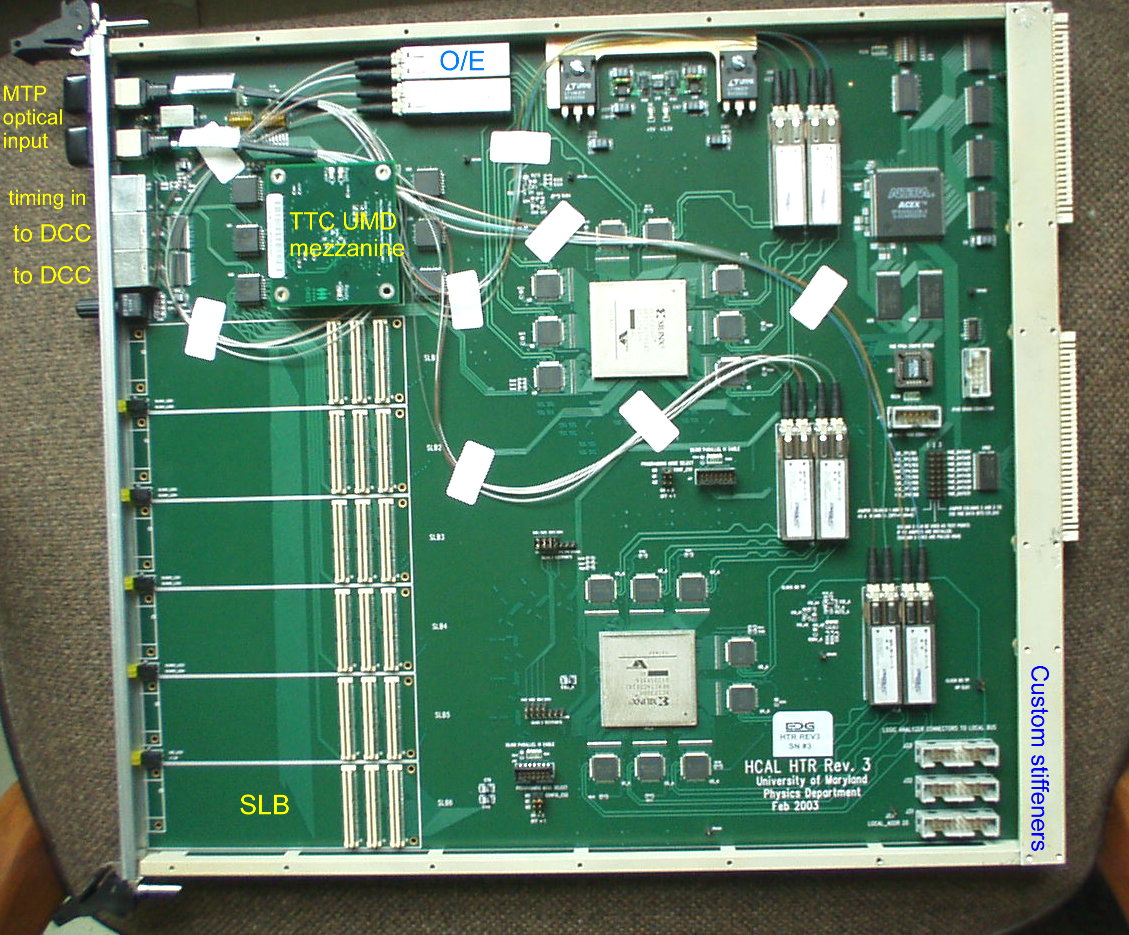
| HTR mother-board | Board-Level changes from HTR prototype , Top View, mechanics by Rich Baum, Timing scheme, Optical input, Short-SLB |
| Main FPGA | HTR Main FPGA description with data formats (in normal mode) , Histogramming mode |
| VME FPGA | Specs, CMS rules for VME (FPGA) interface & available HAL software (included in XDAQ) |
| TTC-PMC mezzanine | see http://www.physics.umd.edu/hep/HTR/TTC-PMC/ |
| VME control software | VME FPGA (Altera) Address Map , Main FPGA (Xilinx) Sub-Address Map , Linux command-line software |
| Xilinx Project | PROM file | FPGAversionN (decimal) |
Notes |
| HTRev3_v21.zip |
HTRev3_v21.mcs | 21 |
-
40 MHz
input (as if QPLL is used) - histogramming firmware integrated - improved L1A receiving circuit (registering with 80 MHz clock) - VME-readable L1A count ("event number") register. - in Histo mode: option to rotate or select 2 fibers |
| HTRev3_v24.zip |
HTRev3_v24.mcs | 24 |
- General review and code
cleaning. - stretched LED Er - BCN is 16-bit now. Trigger_Type moved to Ext. Header6 [7:4] - Optical Signal_Detects (stretched) connected to register 8 - added InSpyFIFOempty on bit[18] of InSpyFIFOs - reg. PipeLength[7:0] can have any value, including 0 (shift by 2 compared to earlier ver.) - L1A synchronization circuit (v21) used also for TTC commands - R/W of LUTs of Trigger-Path (need Altera VME version 0x20 or higher) - Trigger-Path LUTs power-up with values such that Din=Dout - monitor Synchronization Fifo Empty flags and report on the Daq-Data Format as:
|
| HTRev3_v25.zip |
HTRev3_v25.mcs |
25 |
Histogramming mode: Auto fiber fix, fiber number changes after tx to DCC |
| HTRev3_v27.zip | HTRev3_v27.mcs | 27 |
- Histogr. mode: fixed bug "CapID4 bin31". - Changed timing of L2-output (phase of clock and source termination). - Trigger Path latency reduced by 2 BXs. |
|
HTRev3_v29.zip |
HTRev3_v29.mcs |
29 |
- Xilinx DLL fed by TTCrx clock (rather then differential RX_CLK) - implemented Dick's idea for Sync FIFO: wait that the link is established; make sure the FIFO is empty; write 1 word without reading; then start to read (and write) continously. Repeat if DLL unlock. This scheme increase a little the latency, but should avoid later increases due to jitter. - Front-panel clock LED is steady ON in case of TTCrx, DLL problems. - DLL self-reset. - Added DLL unlock counter (availble over VME and on DAQ-data). - keep Error Accumulators to MAX value when overflow. *BUG* observed in bld186 (Error Accumulators count strangly over 12-bits) and in H2 (problems talking to DCC). |
| HTRev3_v30 | HTRev3_v30.mcs | 30 |
Added switch to allow histogramming of QIE mantissa regardless of exponent (bit2 of CSR). Built from v27. |
| HTRev3_v31 | HTRev3_v31.mcs | 31 |
Built from v29. Changes: use differential RX_CLK instead of TTCrx clock. |
| HTRev3_v35 | HTRev3_v35.mcs | 35 |
Tied Hard_rst to asynchronous fifo reset to fix latency alignment issues seen in H2 in the spring of 2004. Built from v30. |
| HTRev3_v38.zip | HTRev3_v38.mcs | 38 |
Fixed ability to accept TTC broadcast commands [found later that this was a termination problem on the board], and changed the list of commands decoded. Built from v35. |
| HTRev3_v39.zip | HTRev3_v39.mcs | 39 |
Fixed several problems with 38: implemented spy startstop via CSR just like in Rev4 (software compatibility); added TTCLASTCommand (somehow it got lost); changed TTC counter registers to have same addresses as for Rev4; assorted UCF stuff. Built from v38. |
| HTRev3_v51.zip | HTRev3_v51.mcs | 51 |
Big changes. This firmware does ONLY histogramming mode. And, it has the ability to set thresholds, but these thresholds are applicable to all 24 histograms at the same time (no ability to define different thresholds for different QIE/Capid. Built from v38. |
| HTRev3_v63.zip | HTRev3_v63.mcs | 63 |
Built from version 51, this version has a first try of filtering on the data from 3 successive time buckets: below, above, below (with respect to thresholds). |
| HTRev3_v64.zip | HTRev3_v64.mcs | 64 |
Built from version 63, this version does the filtering with 2 histogramming thresholds: a high threshold for requiring the signal be greater than some value, and a low threshold for requiring that the "pedestal" be smaller than a value. The DCC data header is changed to keep track of these thresholds, and the firmware version is there as well for the software. |
| Altera Project (by Drew Baden) |
FPGA version |
Notes
|
| 2003-04-23.zip |
0x1F |
No Local Bus access to Trigger LUTs and SLBs |
| 2003-06-30.zip |
0x20 | Local Bus Access to LUTs in Trigger Path and
SLB |
STATUS
3 Boards submitted - 14 Feb 2003 - Manufacturing files_Rev2 by Hans Breden
-PCB manufacturer - PCB assembly house
3 Boards received- 5 Mar 2003 [tested: FPGA
config from cable and VME, FE-inputs, Xilinx DLL x2]
30 Boards sumbitted - 20 Mar 2003 - Manufacturing
files Rev3 , schematic [changes: individual TLK2501 enable,
TTCready/reset, xilinx config circuitry]
First Rev3 board received - 17 Apr
One Rev3 board sent to BU - 25 Apr
14 boards sent to Cern and used for Test Beam - May 2003
TESTS
Power dissipation of one board with firmware, clocks, TTC mezzanine,
without SLBs and input data (this should be irrelevant) = 25 W.
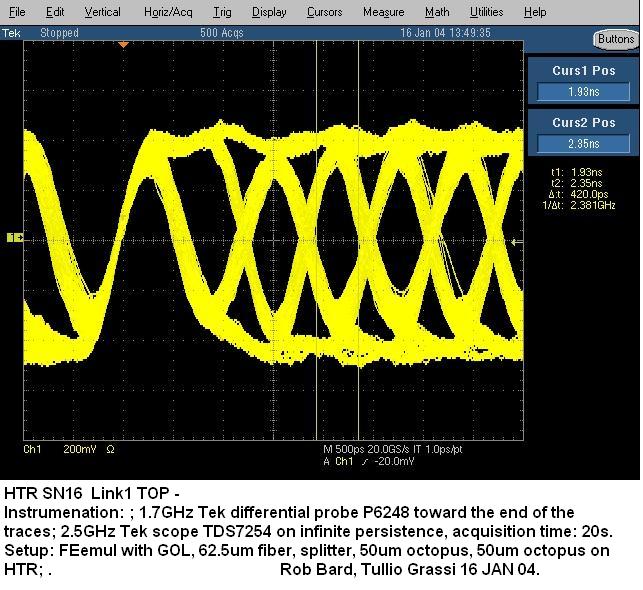
- Eye pattern of
HTR SN16 ch. 1 TOP, triggered by itself
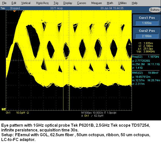
- Eye pattern of
Optical path only, with ribbon cable, triggered by itself
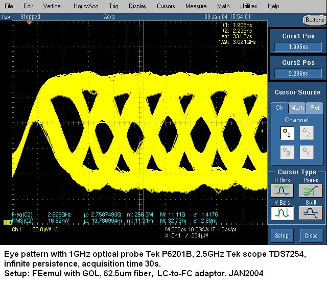
- Eye pattern of
Optical path only, with single fiber, triggered by itself
Trigger Primitives at 80 MHz
- Latency comparison [Aug04]: on H2/CMSMOE3 we loaded three HTR_Rev3 with
three different firmware, applied the same settings and
looked at the position of the center-of-mass of LED pulses:
HTRev3_v27 [synchronization fifo reads and writes at all
times] --> TimeSlice 8.8
HTRev3_v31 [sync. fifo writes ~1 word before starting to read and
write] --> TimeSlice 8.8 or 9.8
HTRev3_v37 [sync. fifo has an external reset] --> TimeSlice 11.8
NB: based on other consideration we believe that any version can show a
variation by 1 clock tick, depending on external delays.
KNOWN PROBLEMS:
- TTC messages unreliable. Fix: remove R220 R263-271 R274-276.
- timing cable from Fanout must be plugged before Xilinx
configuration (usually at power-up).
- Do not use board ID switches (-> short circuit).
- byte swap on VME D32 access.
- the board marginally takes 2 slots (thick part on the bottom
side). To plug adjacent HTRs, put them from right to left.
- plugging the wrong cables in the RJ45 connectors can do permanent
damage.
- The board is not hot-swappable.
- Rarely at powerup FPGAs do not get configured (LEDs will not light up).
Present fix is to power-cycle.
Tullio Grassi - June 2004 - update this page
Return
to my HCAL CMS page