Histogramming Firmware - Rev 3 HTR Boards (2003)
There are 2 different versions of this firmware. The link provided
is a zip file that contains the firmware for the Xilinx FPGA
on the HTR.
-
4-channel histogramming
- full histogramming on the all 8 fibers, but only 4 are filled and
read out at a time. Cycling is automatic.
-
use HTR firmware up to version 17.
-
2-channel histogramming - full histogramming on all 8 fiber inputs,
but only 2 at a time. The particular fiber is selected over vme
(see below).
-
use HTR firmware version 18.
Each fiber input to the HTR contains information from 3 different QIEs,
and each QIE has 4 different capacitors. This makes a total of 12
different inputs which need to be histogrammed on a given fiber.
There are 8 fibers, giving a total of 96 histograms needed. The Xilinx
internal RAM is limited, so we cannot histogram all 12 QIE/Capids
from all 8 fibers simultaneously. Also, the 2003 version of the
DCC
(which has the Slink-64 capability) will not support event sizes
greater than around 400 dwords (1600bytes). So for the 2003
testbeam, we have 2 different versions of the firwmare: one
version which will make histograms for 4 fibers at a time, send the
histograms to the DCC when a L1A is received, then make histograms for
the other set of 4, and so on, alternating indefinitly. However, this
version will not work with the 2003 DCC. The other
version, used for the HF, will only histogram 2 fibers at a time,
which will work with the DCC (given firmware changed on July 23, 2003).
Instead of the fibers alternating indefinetly (1+2, then 3+4, then
5+6, then 7+8) in this version you have to write to localbus (and VME
address space) registers 0xF0 and 0xF4 to set which fibers to histogram.
The HTR will then send data corresponding to the histograms to these
two fibers. The data has a header which will tell you which fibers
are being histogramed in the 2-histogram data block. Note that the
header values go from 0 to 7, but often people speak of fibers 1-8.
The correspondance is obvious!
Implementation
Each distinct QIE/CAPID on any given fiber appears once every 4 clock cycles
due to the rotation cap id's. This gives us 4 clock ticks in which
to perform the histogram filling. For each QIE/CAPID pair, 32 16-bit
words of distributed RAM are allocated. When the particular capid
appears, the mantissa is used as a lookup into distributed RAM for the
frequency of that particular value appearing. The number retrieved
is incremented and restored in the same memory location. This is
implemented with a state machine that does its job in 4 clock ticks, ready
for the next appearance of the particular QIE/CAPID. Each QIE/CAPID
distributed RAM (the histogram) is distinct from all others in the firmware
implementation.
Note that unlike the 2002 version of the HTR firmware, the 2003
version
will do both regular data and histogramming, set by writing 0x1 to the
VME control
register 0xC (see the
HTR
FPGA address map).
Powerup: At powerup, or on a hard reset (VME write
of 0x1 to LocalBus CSR, address 0x10 on the LocalBus), histogramming is
disabled -- regular data taking is the default.
VME configuration needed to implement
histogram: There are only 2 things you have to do in
order to get histograms to be filled and written to the DCC:
-
Set the HTR card number (VME write to LocalBus address
0x20, HTRsubmodN in the documentation). The lower byte of this word
will be written into the header of the data sent to the DCC (see below).
-
Global Enable.
Global enable is the logical AND of both the VME Start and setting
the HTR to go into histogram mode. The VME start is accomplished by
writing a 0x4 to LocalBus CSR (0x10), same as always. The histogram
mode is set by writing a 0x1 into Control Register (CntrReg) 0xC.
Readout
Readout is (at this time) only via the DCC:
Readout via DCC: At powerup, or on a hard reset
(VME write of 0x1 to LocalBus CSR, address 0x10 on the LocalBus), the HTR
mode is for regular (non-histogramming) data taking. To start
histogramming, issue the proper VME commands as described above - VME_Start and VME_Stop along with setting
histogram mode by writing a 0x1 to LocalBus CntrReg 0x10 controls the
entire histogramming. Transmission to the DCC is always via receiving
L1A.
-
Since each bin is described by a 16-bit word, we have to limit the histograms
such that there are no more than 65535 (216 -1) entries in any
one histogram. Since there are histograms for each capid, and
each capid appears once every 4th clock cycle (using the ~35MHz clock),
then histogram filling will be disabled 262,143 (218-1) clock
cycles after beginning, or approximately 7.5ms (262143/f where f is the
actual clock frequency run at the testbeam). Actually, to be
safe, we stop the histogramming after a maximum number of fills which is
less than 65535 fills, since there are a few setup clock ticks and we don't
want to be on the edge. This will mean that if you used the simulator
and sent the same value every time, the resulting histogram will have something
like 65532 or 65533 or 65534, etc., in the single bin. This
was checked phenomenologically. Or, in other words, each histogram
that you will have in the end will have a total of almost, but not quite,
65535 counts integrated over all bins.
-
As soon as the filling is complete, an internal enable
is released, and a signal is sent to the module that controls sending data
to the DCC. This module reads the histograms from all fibers one
bin at a time, filling FIFOs. Each memory read (each bin) is followed
by a write to the FIFO input, and a write of 0x0 to the bin to clear the
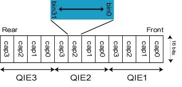
memory so we are ready for the next cycle. Each FIFO contains the
entire set of histograms from a given fiber: 3 QIE x 4 CAPID = 12
histograms, x 32 words (16-bit) = 384 deep, packed as shown in the figure.
-
As soon as the fifo's are filled, the module then reads the FIFOs and sends
data to the DCC. The reason for the intermediate FIFO stage is to
allow data to be sent to the DCC on each clock edge.
Synchronization with source position:
In order to try to synchronize the source posistion with the histogram,
the following has funcctionality has been added:
-
The HTR has a LEMO input for L1A as well as an RJ45 L1A input. Every
time the source position is read out, a pulse (between 100ns and a microsec
or so) should be sent to the HTR in ether the LEMO L1A or the RJ45
input. Internally, the two L1As are or'd together so you can use
either one. This pulse will be used to latch the event number
of the current histogram (EVN_LATCHED). Note that this event number
(EVN) is incremented every time histogram FIFOs are reset, which always
happens after the block of histograms is sent to the DCC. That is,
EVN will be 0 on the first histograms sent to the DCC (fibers 1-4 for the
8-channel firmware) and 1 for the next histogram (fibers 5-8) and so on.
-
The event number EVN will change only every ~7.8ms. The latched EVN
will be stored in the data stream as described below.
DCC Data Format: The data sent to the DCC will
have exactly the same format as the data sent using the regular firmware,
namely a 6-word header followed by data followed by a 2-word trailer, with
each word having 16-bits. The format of each is:
-
Header
- Word 1: {8'h0,evn[7:0]}
- bottom 8 bits are the bottom 8 bits [7:0] of a 24-bit event number (EVN)
- top 8 bits are all zero
- Status bits: 2'b11
- Word 2: evn[23:8]
- top 16 bits [19:8] of the event number (EVN)
- Status bits: 2'b10
- Word 3: MSB: {0,Fiber2[2:0], 0,Fiber1[2:0]}
LSB: {0,0,0,StRq,0,0,1,0}
- the MSB is 0, the next bit is 1 for histogramming mode, followed by
2 0's, then a decoded TTC command called StRq, followed by 3 0's making
up the high byte of the 16-bit word. The low byte contains the fiber
numbers for the 2 fibers. Each of the 2 numbers is 3-bits, so it goes
from 0 to 7 for fibers 1 to 8 respectively.
- Status bits: 2'b10
- Word 4: {ORN,[19:12],hcn[7:0]}
- Bottom 8 bits are the heater card number as described above.
- Top 8 bits, usually reserved for the orbit number, are not used
for histogramming mode.
- Status bits: 2'b10
- Word 5: {trigger_type[3:0],BCN[11:0]}
- The bottom 12 bits are reserved for the bunch crossing
number.
- The top 4 bits are the trigger type. This tells you whether the
L1A came in from the TTC (set to 1) or via a VME command (set to 2).
- Status bits: 2'b10
- Word 6: {14'h0,DLL_lock,TTC_Ready}
- All bits are zero except bits 0 and 1, used mostly for debugging.
- Data.
-
Each successive data word as is read from the FIFO, therefore the data
is packed exactly as the FIFO is packed. See above.
- Status bits: 2'b10
- Trailer
- Words 1-8: Mostly used for regular data...ignore here
- Arrival time (BCN) of Bzero from fiber, used to study latency.
Irrelevant here.
- Status bits: 2'b10
- Pretrailer 3: {16'h0}
- All bits are 0.
- Status bits: 2'b10
- Pretrailer 2: {word count}
- This word should always be 786.
The word count = 6Header + Data + 8BCN0s + 4
Trailer words. Histograms of 2 fibers
results in 2 x 12 x 32 = 768 words, so the word count will be
768 + 6(H) + 8(BCN0) + 4(T) = 786.
- Status bits: 2'b10
- Pretrailer 1: {16'h0}
- All bits are 0.
- Status bits: 2'b10
- Trailer: {EVN[7:0],8'h0}
- Same bottom 8 bits of the EVN (see 1st header word) are in the
upper 8 bits of this word, followed by all 0s in the lower 8 bits.
- Status bits: 2'b01
Last modified 7/23/03 Drew Baden