March Graduate Blog- Willie Merrell
February Graduate Blog- Young Soo Yoon
Andrew York-Atomic Molecular and Optical Physics
Experimental physics loves the extreme. Maryland research thrives on the coldest atoms the fastest particles and the smallest electronic devices. When you have a new toy that lets you do something that was impossible twenty years ago, it's a lot easier to come up with exciting and original ideas. Our lab is no different.
The heart of our lab is a pulsed laser amplification chain that lets us generate some of the most intense electric fields in the world. Our main laser produces pulses of light 50 femtoseconds long containing 100 millijoules, and can be focused to a spot smaller than 10 microns. The electric field of one of our focused pulses is more than ten times stronger than the field that binds an electron to a hydrogen nucleus, but each pulse contains so little energy it would take more than 20,000 of them to boil a gram of water. If you accidentally block our beam with your hand, you don't feel your hand heat up, you just hear a snapping sound as you smell what used to be a thin layer of your skin.
Ultraintense fields have gotten a lot cheaper in the past twenty years. The technique of chirped-pulse amplification, pioneered in the mid-eighties, allows small labs like ours to generate huge field strengths on a reasonable budget. The same intensities produced by a $176 million football-field-size government project in 1984 can now be purchased off the shelf for about $1 million, and fits on a tabletop. Because so many labs can afford femtosecond-scale millijoule-level lasers, new ideas for applications can spread rapidly. Quite a few applications have been found, including micromachining, coherent x-ray generation, terahertz generation, nonlinear microscopy, electron acceleration, and photochemistry. One of our lab's projects is to improve the efficiency and peak intensity of coherent x-ray generation by femtosecond lasers. The difference between a coherent x-ray beam and an incoherent one is the same as the difference between a light bulb and a laser: hard to explain quickly, but very important to scientists. Bright sources of coherent x-rays are useful for medical imaging, lithography, biology research, and plasma physics. Bright sources of coherent x-rays are also traditionally large and expensive shared facilities like synchrotrons or free electron lasers.
Femtosecond lasers offer an appealing alternative that brings coherent x-rays into small labs. When you focus an intense laser pulse into a low-pressure gas, (Figure 1), coherent ultraviolet and x-ray radiation is produced at the focal spot of the beam . The mechanism is simple: the intense electric field of the laser rips electrons away from gas atoms and slams them back into the parent atom half an optical cycle later. The violent acceleration of the electron during recombination can produce very short-pulse, high-frequency radiation. The drawback of the method in Figure 1, however, is efficiency.
xxxxxxxx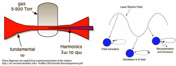
xxxxxxxFigure 1
Only a very small spot at the focus of the beam is intense enough to produce x-rays, so the resulting beams are very weak. Our group has demonstrated extending the size of the intense focal region by guiding laser pulses in hollow optical fibers made of plasma (see Figure 2), and has also proposed several schemes for efficiently generating coherent x-rays using these fibers. These optical plasma fibers are specially shaped sparks that guide light exactly like glass fiber optics. Plasma fibers, however, can guide ultraintense laser pulses that would destroy any glass fiber in a single shot. Since the plasma fiber could be extended to huge lengths, the size of the focal region doesn't limit conversion efficiency any more. A new problem arises, however: phase matching. In general, infrared laser pulses and the x-rays they generate don't go the same speed in a mixture of neutral and ionized gas. If the x-rays slip ahead of the generating laser pulse by half a wavelength, they destructively interfere with any new x-rays generated by the laser. For a given mismatch in speed, the "dephasing length" is how far the laser and the x-rays can go before they slip out of phase. Making the fiber any longer than the dephasing length is pointless and actually decreases total efficiency. By carefully manipulating the size and composition of the spark in Figure 2, we could minimize the x-ray/laser pulse speed mismatch and thus make the dephasing length as long as possible. This requires careful microscopic control of the spark shape and the injection of the laser pulse, and is annoying to do in practice.
xxxxxxxxxxxxxxxxxxxxxx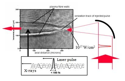
xxxxxxxxxxxxxxxxxxxx Figure 2
Recently, we decided to try to make a diameter-modulated plasma fiber, and we succeeded (see Figure 3). The modulated waveguide abandons dispersion-based speed-matching and allows the x-rays and laser pulse to drift in and out of phase with each other. The spacing of the modulations is carefully chosen to be one dephasing length long. This way, when the pulse interferes constructively with the x-rays, the fiber diameter is small and the laser energy is crunched into an intense spot. When the pulse is destructively out of phase with the x-rays, the fiber diameter is large and the laser is spread out into a large, weak beam. Unlike the unmodulated case, each dephasing length generates net x-rays, so extending the fiber for many dephasing lengths increases total efficiency. We're currently working on generating x-rays in the modulated plasma fiber. Since a plasma fiber has no damage threshold, we should be able to use a laser pulse that is arbitrarily intense. More intense pulses can produce much shorter wavelengths and higher conversion efficiencies, so this is a very exciting experiment. Check in with us at lasermatter.umd.edu in a few months to find out how it turns out!
xxxxxxxxxxxxxxxxxxxxxxx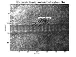
xxxxxxxxxxxxxxxxxxxxxxx Figure 3
|