The previous project has the BASYS3 send a digitized voltage to the RPi by pushing a button on the board. In this project we will have the transfer completely controlled by the RPi, which means we will have to enhance the FPGA interface to be able to accept "commands" from the RPi to latch the voltage and send it along.
Make a new Vivado project, call it something like "voltmeter2". The top level (call it top.v) will have the same inputs as in the previous project, however this time we will use the LEDs to show what is being transmitted to the RPi, so they do not have to be declared as "reg" (we will use the assign). Also, let's input the slide switches as sw so that we can have the RPi read them, that way we can check if the transfer is happening ok.
The instantiation will be:
module top(
    input clock,            // system clock
    input reset,            // BTNR
    input version,          // BTNU
    input adc_n, adc_p,     // VCAUX 6, P and N
    input [15:0] sw,        // slide switches
    output [15:0] led,      // 16  onboard LEDs above the switches
    output [6:0] segment,   // 4 digit LED display
    output dp,              // "." next to each LED digit
    output [3:0] digit,     // which of the 4 digits to drive
    output [7:0] JB,        // PMOD for debugging
    input rx,               // UART receive
    output tx               // UART transmit
    );
    parameter VERSION = 'h0011;
For clocking, we will need the same as in the previous project: a 25MHz clock for the uart modules and state machines, and a 104MHz clock for the XADC. So go ahead and generate a clock_104 module just like in the previous project and instantiate like this:
    //
    //  make a slower clock for the UART transmitter and for the FSM
    //  below that controls it.   We do this because the logic analyzer
    //  is slow too, it will only look at 8 wires at 25MHz.   So if we
    //  divide the system clock by 4, that will give us a 25MHz clock
    //  and that should do nicelly, and it will make clocks_per_bit come
    //  out as an integer
    //
    reg [1:0] count2 = 0;
    always @ (posedge clock) count2 <= count2 + 1;
    wire clock25;
    BUFG clk25buf (.I(count2[1]), .O(clock25) );
    //
    //  generate a 104MHz clock for the XADC so we can get samples at 1MHz
    //
    wire locked, clock104;
    clock_104 XADC_CLOCK(
        .reset(reset),
        .locked(locked),
        .clk_in1(clock),
        .clk_out1(clock104)
    );
And drive the 4 7-segment LEDs like before:
    //
    //  next drive the 4 7-segment displays
    //
    wire [15:0] display_this;
    display4 DISPLAY (
        .clk100(clock),
        .number(display_this),
        .digit(digit),
        .segments(segment),
        .period(dp)
        );
Next instantiate the uart tx and rx modules:
    //
    //  instantiate the UART receiver.  run with the 50MHz clock so that
    //  we can run the transmitter FSM at 100MHz and not get lost
    //
    wire dv;
    wire [7:0] rx_data;
    uart_rx RECEIVER (
        .i_Clocks_per_Bit('d25),
        .i_Clock(clock25),
        .i_Reset(reset),
        .i_Rx_Serial(rx),       // tied to FPGA rx output
        .o_Rx_DV(dv),
        .o_Rx_Byte(rx_data)
        );
    //
    //  instantiate the UART transmitter
    //
    wire tx_active, tx_done;
    wire do_transmit;
    wire [7:0] transmit_byte;
    uart_tx TRANSMITTER (
        .i_Clocks_per_Bit('d25),
        .i_Clock(clock25),
        .i_Reset(reset),
        .i_Tx_DV(do_transmit),
        .i_Tx_Byte(transmit_byte),
        .o_Tx_Active(tx_active),
        .o_Tx_Serial(tx),       // tied to FPGA tx output
        .o_Tx_Done(tx_done)
        );
Note that dv will go high when the uart_rx module has a new byte received, and do_transmit will go high when the state machines wants to send something to the RPi.
Next comes the XADC block, which you should make by new (see Using the FPGA ADC) even if you have it from copying the previous project Voltmeter: FPGA and RPi), since I've seen weird things from just using the copy. Call this new one myxadc in the "Components Name" text field. Be sure that the input clock is clock_104:
    //  here is the XADC block
    //
    wire [6:0] daddr_in = 7'h16;
    wire adc_ready, isbusy, adc_data_ready, eos_out, alarm;
    wire [15:0] adc_data;
    wire [4:0] channel_out;
    myxadc XADC_INST (
        .daddr_in(7'h16),   // specifies vcaux6 pints to digitize
        .dclk_in(clock104),    // 50MHz clock
        .den_in(adc_ready), // tied to adc_ready, tells adc to convert, tieing causes continuous conversions
        .di_in(16'h0),      // to set the data to something, not used here
        .dwe_in(1'b0),      //  set to enable writing to di_in, which we don't want to do
        .vauxp6(adc_p),     //  positive input to digitize
        .vauxn6(adc_n),     //  negative input to digitize
        .busy_out(isbusy),  // tells you the adc is busy converting
        .channel_out(channel_out[4:0]), // for using more than 1 channel, tells you which one.  not used here
        .do_out(adc_data),      // adc value from conversion
        .drdy_out(adc_data_ready),  //tells you valid data is ready to be latched
        .eoc_out(adc_ready),   //  specifies that the ADC is ready (conversion complete)
        .eos_out(eos_out),     //  specifies that conversion sequence is complete
        .alarm_out(alarm),      // OR's output of all internal alarms, not used here
        .vp_in(1'b0),           // dedicated analog input pair for differential, tied to 0 if not used
        .vn_in(1'b0)
    );
    //
    // wait for XADC to tell you something is ready to latch. note this means continuous latching
    //
    reg [15:0] r_adc_data;
    always @ (negedge isbusy) begin
        if (reset) r_adc_data <= 16'h0;
        else r_adc_data <= adc_data;
        end
    //
    //  make a ~1Hz clock so we can run the LED display slower
    //
    reg [26:0] counter;
    reg [15:0] s_adc_data;
    always @ (posedge clock) begin
        if (reset) counter <= 0;
        else counter <= counter + 1;
        end
    wire clock_1hz = counter[26];
    always @ (posedge clock_1hz) s_adc_data <= r_adc_data;
    assign display_this = version ? VERSION : s_adc_data;
You can see that we are latching the XADC ADC value adc_data into r_adc_data using the isbusy neagative edge, and we have a 1Hz clock to latch r_adc_data into s_adc_data, which goes into display_this for the 7-segment displays.
We will use the same state machine as in the Voltmeter: FPGA and RPi project to send data to the RPi, which goes like this:
    //
    //  now make a state machine to deal with transmitting 2 bytes
    //
    reg [2:0] tx_state;     // 7 states so 3 bits will do
    localparam [2:0] TX_WAIT=0, TX_BYTE1=1, TX_DO1=2, TX_WAIT1=3, TX_BYTE2=4,
                    TX_DO2=5, TX_WAIT2=6;
    reg doit;
    wire [16:0] transmit_word;
    wire begin_transfer;
    reg [7:0] tx_data;
    always @ (posedge clock25) begin
        if (reset) begin
            tx_state <= TX_WAIT;
            doit <= 0;
            tx_data <= 0;
        end
        else
            case (tx_state)
                TX_WAIT: begin
                    if (begin_transfer) tx_state <= TX_BYTE1;
                    else tx_state <= TX_WAIT;
                    doit <= 0;
                    tx_data <= 0;
                end
                TX_BYTE1: begin
                    tx_data <= transmit_word[7:0];
                    tx_state <= TX_DO1;
                end
                TX_DO1: begin
                    doit <= 1;
                    tx_state <= TX_WAIT1;
                end
                TX_WAIT1: begin
                    doit <= 0;
                    if (tx_done) tx_state <= TX_BYTE2;
                    else tx_state <= TX_WAIT1;
                end
                TX_BYTE2: begin
                    tx_data <= transmit_word[15:8];
                    tx_state <= TX_DO2;
                end
                TX_DO2: begin
                    doit <= 1;
                    tx_state <= TX_WAIT2;
                end
                TX_WAIT2: begin
                    doit <= 0;
                    if (tx_done) tx_state <= TX_WAIT;
                    else tx_state <= TX_WAIT2;
                end
            endcase
    end
    assign do_transmit = doit;
    assign transmit_byte = tx_data;
Note that for this state machine, we use begin_transfer as the trigger to start transfering the 2 bytes contained in transmit_word. These are both controlled in the next state machine.
When the RPi sends a byte to the FPGA, it will send 8 bits, so we can use those 8 bits as commands that the FPGA will receive and respond to. This is common in data acquisition systems - data can also be commands. The first thing you have to do is figure out what commands you want to send, and assign bits (or combination of bits) from the 8 bit data word. The main command that we want the RPi to send will be to latch the data from the XADC block and send the 2 bytes along, so let's assign this to bit 0 (LSB) of the data word. That means that if that bit is asserted, the FPGA will send the data from r_adc_data. Let's also make a command that tells the FPGA to send the data on the 16 slide switches, so that we can be sure things are working properly. We can also have the FPGA send the firmware version. So we have 3 possible values for the FPGA to send, which means we need 2 bits to encode those 3, so we can arbitrarily use the lower 3 bits to have the following meaning:
Now all we will need to do is add a state machine that will receive uart data, decode it, and decide what to do with it. This new state machine will also drive the transmit state machine that is triggered by the transmit button in the voltmeter project.
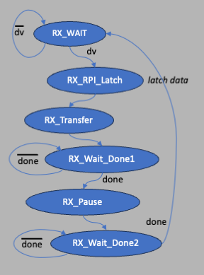
The new state machine should look like this:
and will have the following states:
//
    //  next comes the uart receive state machine
    //
    reg [2:0] rx_state;
    localparam [2:0] RX_WAIT=0, RX_RPI_LATCH=1, RX_Transfer=2,
       RX_PAUSE=3, RX_WAIT_Done1=4, RX_WAIT_Done2=5;
    reg start_tx;
    wire [1:0] latch_what = {rx_data[2],rx_data[1]};
    reg [15:0] transmit_this;
    always @ (posedge clock25) begin
        if (reset) begin
            start_tx <= 0;
            rx_state <= RX_WAIT;
            transmit_this <= 0;
        end
        else
            case (rx_state)
                RX_WAIT: begin
                    start_tx <= 0;
                    transmit_this <= 0;
                    if (dv && rx_data[0]) rx_state <= RX_RPI_LATCH;
                    else rx_state <= RX_WAIT;
                end
                RX_RPI_LATCH: begin
                    rx_state <= RX_Transfer;
                    case (latch_what)
                        2'b00: transmit_this <= 'hEEEE;          // error!
                        2'b01: transmit_this <= r_adc_data;
                        2'b10: transmit_this <= sw;
                        2'b11: transmit_this <= VERSION;
                    endcase
                end
                RX_Transfer: begin
                    start_tx <= 1;
                    rx_state <= RX_WAIT_Done1;
                end
                RX_WAIT_Done1: begin
                    if (tx_done) rx_state <= RX_PAUSE;
                    else rx_state <= RX_WAIT_Done1;
                end
                RX_PAUSE: begin
                    rx_state <= RX_WAIT_Done2;
                end
                RX_WAIT_Done2: begin
                    if (tx_done) rx_state <= RX_WAIT_Done2;
                    else rx_state <= RX_WAIT;
                end
            endcase
    end
We have a 3-bit state rx_state (6 states so we need 3 bits), a register called start_tx that ties into the TX state machine, this will be its trigger. Then a 2-bit wire called latch_what that is made of a concatenation of bits 1 and 2 of the data sent as a command, used by the state machine in the RX_RPI_LATCH state to know what to grab. Then a register called transmit_this that is used by the TX state machine to send to the RPi, one byte at a time. One thing to always watch out for: when you declare latch_what, if you forget to declare it as a 2-bit wire and instead make the following mistake leaving out the wire [1:0] and just saying wire:
wire latch_what = {rx_data[2],rx_data[1]};
then the synthesized code will only look at the lower bit and you won't get what you want in the RX_RPI_LATCH stage. It's not a bug in the system, it's more of a weakness.
The full code should look something like this:
`timescale 1ns / 1ps
//////////////////////////////////////////////////////////////////////////////////
// Company:
// Engineer:
//
// Create Date: 09/23/2023 03:41:41 PM
// Design Name:
// Module Name: top
// Project Name:
// Target Devices:
// Tool Versions:
// Description:
//
// Dependencies:
//
// Revision:
// Revision 0.01 - File Created
// Additional Comments:
//
//////////////////////////////////////////////////////////////////////////////////


module top(
    input clock,            // system clock
    input reset,            // BTNR
    input version,          // BTNU
    input adc_n, adc_p,     // VCAUX 6, P and N
    input [15:0] sw,        // slide switches
    output [15:0] led,      // 16  onboard LEDs above the switches
    output [6:0] segment,   // 4 digit LED display
    output dp,              // "." next to each LED digit
    output [3:0] digit,     // which of the 4 digits to drive
    output [7:0] JB,        // PMOD for debugging
    input rx,               // UART receive
    output tx               // UART transmit
    );
    parameter VERSION = 'h0011;
    //
    //  make a slower clock for the UART transmitter and for the FSM
    //  below that controls it.   We do this because the logic analyzer
    //  is slow too, it will only look at 8 wires at 25MHz.   So if we
    //  divide the system clock by 4, that will give us a 25MHz clock
    //  and that should do nicelly, and it will make clocks_per_bit come
    //  out as an integer
    //
    reg [1:0] count2 = 0;
    always @ (posedge clock) count2 <= count2 + 1;
    wire clock25;
    BUFG clk25buf (.I(count2[1]), .O(clock25) );
    //
    //  generate a 104MHz clock for the XADC so we can get samples at 1MHz
    //
    wire locked, clock104;
    clock_104 XADC_CLOCK(
        .reset(reset),
        .locked(locked),
        .clk_in1(clock),
        .clk_out1(clock104)
    );
    //
    //  next drive the 4 7-segment displays
    //
    wire [15:0] display_this;
    display4 DISPLAY (
        .clk100(clock),
        .number(display_this),
        .digit(digit),
        .segments(segment),
        .period(dp)
        );
    //
    //  instantiate the UART receiver.  run with the 50MHz clock so that
    //  we can run the transmitter FSM at 100MHz and not get lost
    //
    wire dv;
    wire [7:0] rx_data;
    uart_rx RECEIVER (
        .i_Clocks_per_Bit('d25),
        .i_Clock(clock25),
        .i_Reset(reset),
        .i_Rx_Serial(rx),       // tied to FPGA rx output
        .o_Rx_DV(dv),
        .o_Rx_Byte(rx_data)
        );
    //
    //  instantiate the UART transmitter
    //
    wire tx_active, tx_done;
    wire do_transmit;
    wire [7:0] transmit_byte;
    uart_tx TRANSMITTER (
        .i_Clocks_per_Bit('d25),
        .i_Clock(clock25),
        .i_Reset(reset),
        .i_Tx_DV(do_transmit),
        .i_Tx_Byte(transmit_byte),
        .o_Tx_Active(tx_active),
        .o_Tx_Serial(tx),       // tied to FPGA tx output
        .o_Tx_Done(tx_done)
        );
    //
    //  here is the XADC block
    //
    wire [6:0] daddr_in = 7'h16;
    wire adc_ready, isbusy, adc_data_ready, eos_out, alarm;
    wire [15:0] adc_data;
    wire [4:0] channel_out;
    myxadc XADC_INST (
        .daddr_in(7'h16),   // specifies vcaux6 pints to digitize
        .dclk_in(clock104),    // 50MHz clock
        .den_in(adc_ready), // tied to adc_ready, tells adc to convert, tieing causes continuous conversions
        .di_in(16'h0),      // to set the data to something, not used here
        .dwe_in(1'b0),      //  set to enable writing to di_in, which we don't want to do
        .vauxp6(adc_p),     //  positive input to digitize
        .vauxn6(adc_n),     //  negative input to digitize
        .busy_out(isbusy),  // tells you the adc is busy converting
        .channel_out(channel_out[4:0]), // for using more than 1 channel, tells you which one.  not used here
        .do_out(adc_data),      // adc value from conversion
        .drdy_out(adc_data_ready),  //tells you valid data is ready to be latched
        .eoc_out(adc_ready),   //  specifies that the ADC is ready (conversion complete)
        .eos_out(eos_out),     //  specifies that conversion sequence is complete
        .alarm_out(alarm),      // OR's output of all internal alarms, not used here
        .vp_in(1'b0),           // dedicated analog input pair for differential, tied to 0 if not used
        .vn_in(1'b0)
    );
    //
    // wait for XADC to tell you something is ready to latch. note this means continuous latching
    //
    reg [15:0] r_adc_data;
    always @ (negedge isbusy) begin
        if (reset) r_adc_data <= 16'h0;
        else r_adc_data <= adc_data;
        end
    //
    //  make a ~1Hz clock so we can run the LED display slower
    //
    reg [26:0] counter;
    reg [15:0] s_adc_data;
    always @ (posedge clock) begin
        if (reset) counter <= 0;
        else counter <= counter + 1;
        end
    wire clock_1hz = counter[26];
    always @ (posedge clock_1hz) s_adc_data <= r_adc_data;
    assign display_this = version ? VERSION : s_adc_data;
    //
    //  now make a state machine to deal with transmitting 2 bytes
    //
    reg [2:0] tx_state;     // 7 states so 3 bits will do
    localparam [2:0] TX_WAIT=0, TX_BYTE1=1, TX_DO1=2, TX_WAIT1=3, TX_BYTE2=4,
                    TX_DO2=5, TX_WAIT2=6;
    reg doit;
    wire [16:0] transmit_word;
    wire begin_transfer;
    reg [7:0] tx_data;
    always @ (posedge clock25) begin
        if (reset) begin
            tx_state <= TX_WAIT;
            doit <= 0;
            tx_data <= 0;
        end
        else
            case (tx_state)
                TX_WAIT: begin
                    if (begin_transfer) tx_state <= TX_BYTE1;
                    else tx_state <= TX_WAIT;
                    doit <= 0;
                    tx_data <= 0;
                end
                TX_BYTE1: begin
                    tx_data <= transmit_word[7:0];
                    tx_state <= TX_DO1;
                end
                TX_DO1: begin
                    doit <= 1;
                    tx_state <= TX_WAIT1;
                end
                TX_WAIT1: begin
                    doit <= 0;
                    if (tx_done) tx_state <= TX_BYTE2;
                    else tx_state <= TX_WAIT1;
                end
                TX_BYTE2: begin
                    tx_data <= transmit_word[15:8];
                    tx_state <= TX_DO2;
                end
                TX_DO2: begin
                    doit <= 1;
                    tx_state <= TX_WAIT2;
                end
                TX_WAIT2: begin
                    doit <= 0;
                    if (tx_done) tx_state <= TX_WAIT;
                    else tx_state <= TX_WAIT2;
                end
            endcase
    end
    assign do_transmit = doit;
    assign transmit_byte = tx_data;
    //
    //  next comes the uart receive state machine
    //
    reg [2:0] rx_state;
    localparam [2:0] RX_WAIT=0, RX_RPI_LATCH=1, RX_Transfer=2,
       RX_PAUSE=3, RX_WAIT_Done1=4, RX_WAIT_Done2=5;
    reg start_tx;
    wire [1:0] latch_what = {rx_data[2],rx_data[1]};
    reg [15:0] transmit_this;
    always @ (posedge clock25) begin
        if (reset) begin
            start_tx <= 0;
            rx_state <= RX_WAIT;
            transmit_this <= 0;
        end
        else
            case (rx_state)
                RX_WAIT: begin
                    start_tx <= 0;
                    transmit_this <= 0;
                    if (dv && rx_data[0]) rx_state <= RX_RPI_LATCH;
                    else rx_state <= RX_WAIT;
                end
                RX_RPI_LATCH: begin
                    rx_state <= RX_Transfer;
                    case (latch_what)
                        2'b00: transmit_this <= 'hEEEE;          // error!
                        2'b01: transmit_this <= r_adc_data;
                        2'b10: transmit_this <= sw;
                        2'b11: transmit_this <= VERSION;
                    endcase
                end
                RX_Transfer: begin
                    start_tx <= 1;
                    rx_state <= RX_WAIT_Done1;
                end
                RX_WAIT_Done1: begin
                    if (tx_done) rx_state <= RX_PAUSE;
                    else rx_state <= RX_WAIT_Done1;
                end
                RX_PAUSE: begin
                    rx_state <= RX_WAIT_Done2;
                end
                RX_WAIT_Done2: begin
                    if (tx_done) rx_state <= RX_WAIT_Done2;
                    else rx_state <= RX_WAIT;
                end
            endcase
    end
    assign transmit_word = transmit_this;
    assign begin_transfer = start_tx;
    assign led = transmit_this;
    assign JB = {doit,do_transmit,tx_active,tx_done,latch_what[1:0],dv,clock25};
endmodule
The constraints file should be the same as in the previous project, but you will have to add the slide switches:
## clock
set_property PACKAGE_PIN W5 [get_ports clock]
set_property IOSTANDARD LVCMOS33 [get_ports clock]

# rx is pin 4 on JC
set_property PACKAGE_PIN P18 [get_ports rx]
set_property IOSTANDARD LVCMOS33 [get_ports rx]
# tx is pin 1 on JC
set_property PACKAGE_PIN K17 [get_ports tx]
set_property IOSTANDARD LVCMOS33 [get_ports tx]

## Switches
set_property PACKAGE_PIN V17 [get_ports {sw[0]}]
set_property IOSTANDARD LVCMOS33 [get_ports {sw[0]}]
set_property PACKAGE_PIN V16 [get_ports {sw[1]}]
set_property IOSTANDARD LVCMOS33 [get_ports {sw[1]}]
set_property PACKAGE_PIN W16 [get_ports {sw[2]}]
set_property IOSTANDARD LVCMOS33 [get_ports {sw[2]}]
set_property PACKAGE_PIN W17 [get_ports {sw[3]}]
set_property IOSTANDARD LVCMOS33 [get_ports {sw[3]}]
set_property PACKAGE_PIN W15 [get_ports {sw[4]}]
set_property IOSTANDARD LVCMOS33 [get_ports {sw[4]}]
set_property PACKAGE_PIN V15 [get_ports {sw[5]}]
set_property IOSTANDARD LVCMOS33 [get_ports {sw[5]}]
set_property PACKAGE_PIN W14 [get_ports {sw[6]}]
set_property IOSTANDARD LVCMOS33 [get_ports {sw[6]}]
set_property PACKAGE_PIN W13 [get_ports {sw[7]}]
set_property IOSTANDARD LVCMOS33 [get_ports {sw[7]}]
set_property PACKAGE_PIN V2 [get_ports {sw[8]}]
set_property IOSTANDARD LVCMOS33 [get_ports {sw[8]}]
set_property PACKAGE_PIN T3 [get_ports {sw[9]}]
set_property IOSTANDARD LVCMOS33 [get_ports {sw[9]}]
set_property PACKAGE_PIN T2 [get_ports {sw[10]}]
set_property IOSTANDARD LVCMOS33 [get_ports {sw[10]}]
set_property PACKAGE_PIN R3 [get_ports {sw[11]}]
set_property IOSTANDARD LVCMOS33 [get_ports {sw[11]}]
set_property PACKAGE_PIN W2 [get_ports {sw[12]}]
set_property IOSTANDARD LVCMOS33 [get_ports {sw[12]}]
set_property PACKAGE_PIN U1 [get_ports {sw[13]}]
set_property IOSTANDARD LVCMOS33 [get_ports {sw[13]}]
set_property PACKAGE_PIN T1 [get_ports {sw[14]}]
set_property IOSTANDARD LVCMOS33 [get_ports {sw[14]}]
set_property PACKAGE_PIN R2 [get_ports {sw[15]}]
set_property IOSTANDARD LVCMOS33 [get_ports {sw[15]}]

# push buttons
set_property PACKAGE_PIN T17 [get_ports reset]
set_property IOSTANDARD LVCMOS33 [get_ports reset]
set_property PACKAGE_PIN T18 [get_ports version]
set_property IOSTANDARD LVCMOS33 [get_ports version]

# LEDs
set_property PACKAGE_PIN U16 [get_ports {led[0]}]
set_property IOSTANDARD LVCMOS33 [get_ports {led[0]}]
set_property PACKAGE_PIN E19 [get_ports {led[1]}]
set_property IOSTANDARD LVCMOS33 [get_ports {led[1]}]
set_property PACKAGE_PIN U19 [get_ports {led[2]}]
set_property IOSTANDARD LVCMOS33 [get_ports {led[2]}]
set_property PACKAGE_PIN V19 [get_ports {led[3]}]
set_property IOSTANDARD LVCMOS33 [get_ports {led[3]}]
set_property PACKAGE_PIN W18 [get_ports {led[4]}]
set_property IOSTANDARD LVCMOS33 [get_ports {led[4]}]
set_property PACKAGE_PIN U15 [get_ports {led[5]}]
set_property IOSTANDARD LVCMOS33 [get_ports {led[5]}]
set_property PACKAGE_PIN U14 [get_ports {led[6]}]
set_property IOSTANDARD LVCMOS33 [get_ports {led[6]}]
set_property PACKAGE_PIN V14 [get_ports {led[7]}]
set_property IOSTANDARD LVCMOS33 [get_ports {led[7]}]
set_property PACKAGE_PIN V13 [get_ports {led[8]}]
set_property IOSTANDARD LVCMOS33 [get_ports {led[8]}]
set_property PACKAGE_PIN V3 [get_ports {led[9]}]
set_property IOSTANDARD LVCMOS33 [get_ports {led[9]}]
set_property PACKAGE_PIN W3 [get_ports {led[10]}]
set_property IOSTANDARD LVCMOS33 [get_ports {led[10]}]
set_property PACKAGE_PIN U3 [get_ports {led[11]}]
set_property IOSTANDARD LVCMOS33 [get_ports {led[11]}]
set_property PACKAGE_PIN P3 [get_ports {led[12]}]
set_property IOSTANDARD LVCMOS33 [get_ports {led[12]}]
set_property PACKAGE_PIN N3 [get_ports {led[13]}]
set_property IOSTANDARD LVCMOS33 [get_ports {led[13]}]
set_property PACKAGE_PIN P1 [get_ports {led[14]}]
set_property IOSTANDARD LVCMOS33 [get_ports {led[14]}]
set_property PACKAGE_PIN L1 [get_ports {led[15]}]
set_property IOSTANDARD LVCMOS33 [get_ports {led[15]}]
##
## 7 segment display
set_property PACKAGE_PIN W7 [get_ports {segment[0]} ]
set_property IOSTANDARD LVCMOS33 [get_ports {segment[0]} ]
set_property PACKAGE_PIN W6 [get_ports {segment[1]} ]
set_property IOSTANDARD LVCMOS33 [get_ports {segment[1]} ]
set_property PACKAGE_PIN U8 [get_ports {segment[2]} ]
set_property IOSTANDARD LVCMOS33 [get_ports {segment[2]} ]
set_property PACKAGE_PIN V8 [get_ports {segment[3]} ]
set_property IOSTANDARD LVCMOS33 [get_ports {segment[3]} ]
set_property PACKAGE_PIN U5 [get_ports {segment[4]} ]
set_property IOSTANDARD LVCMOS33 [get_ports {segment[4]} ]
set_property PACKAGE_PIN V5 [get_ports {segment[5]} ]
set_property IOSTANDARD LVCMOS33 [get_ports {segment[5]} ]
set_property PACKAGE_PIN U7 [get_ports {segment[6]} ]
set_property IOSTANDARD LVCMOS33 [get_ports {segment[6]} ]
##
## LED period (dot)
set_property PACKAGE_PIN V7 [get_ports {dp}]
set_property IOSTANDARD LVCMOS33 [get_ports {dp}]
##
## digit select
set_property PACKAGE_PIN U2 [get_ports {digit[0]} ]
set_property IOSTANDARD LVCMOS33 [get_ports {digit[0]} ]
set_property PACKAGE_PIN U4 [get_ports {digit[1]} ]
set_property IOSTANDARD LVCMOS33 [get_ports {digit[1]} ]
set_property PACKAGE_PIN V4 [get_ports {digit[2]} ]
set_property IOSTANDARD LVCMOS33 [get_ports {digit[2]} ]
set_property PACKAGE_PIN W4 [get_ports {digit[3]} ]
set_property IOSTANDARD LVCMOS33 [get_ports {digit[3]} ]

## Buttons
set_property PACKAGE_PIN T18 [get_ports version]
set_property IOSTANDARD LVCMOS33 [get_ports version]
set_property PACKAGE_PIN W19 [get_ports latch]
set_property IOSTANDARD LVCMOS33 [get_ports latch]
set_property PACKAGE_PIN T17 [get_ports reset]
set_property IOSTANDARD LVCMOS33 [get_ports reset]

## Pmod Header JXADC
## Schematic name = XA1_P
set_property PACKAGE_PIN J3 [get_ports adc_p ]
set_property IOSTANDARD LVCMOS33 [get_ports adc_p ]
## Schematic name = XA1_N
set_property PACKAGE_PIN K3 [get_ports adc_n ]
set_property IOSTANDARD LVCMOS33 [get_ports adc_n ]

##Pmod Header JB
##Sch name = JB1
set_property PACKAGE_PIN A14 [get_ports {JB[0]}]
set_property IOSTANDARD LVCMOS33 [get_ports {JB[0]}]
##Sch name = JB2
set_property PACKAGE_PIN A16 [get_ports {JB[1]}]
set_property IOSTANDARD LVCMOS33 [get_ports {JB[1]}]
##Sch name = JB3
set_property PACKAGE_PIN B15 [get_ports {JB[2]}]
set_property IOSTANDARD LVCMOS33 [get_ports {JB[2]}]
##Sch name = JB4
set_property PACKAGE_PIN B16 [get_ports {JB[3]}]
set_property IOSTANDARD LVCMOS33 [get_ports {JB[3]}]
##Sch name = JB7
set_property PACKAGE_PIN A15 [get_ports {JB[4]}]
set_property IOSTANDARD LVCMOS33 [get_ports {JB[4]}]
##Sch name = JB8
set_property PACKAGE_PIN A17 [get_ports {JB[5]}]
set_property IOSTANDARD LVCMOS33 [get_ports {JB[5]}]
##Sch name = JB9
set_property PACKAGE_PIN C15 [get_ports {JB[6]}]
set_property IOSTANDARD LVCMOS33 [get_ports {JB[6]}]
##Sch name = JB10
set_property PACKAGE_PIN C16 [get_ports {JB[7]}]
set_property IOSTANDARD LVCMOS33 [get_ports {JB[7]}]
The above project archive can be found
here.
The RPi program will be similar to the voltmeter program made for the previous lab, but now we have to add the ability to transmit information. The code that works is called voltmeter2 and looks like this:
from tkinter import *
import serial
import serial.tools.list_ports
import codecs
import time

root = Tk()


class Application(Frame):
    """ Create the window and populate with widgets """

    def __init__(self,parent):
        """ initializes the frame """
        Frame.__init__(self,parent,background="white")
        self.parent = parent
        self.grid()
        self.create_widgets()
        self.isopen = 0
        self.openPort()

    def create_widgets(self):
        self.buttonQ = Button(self, text="Quit")
        self.buttonQ["command"] = self.quitit
        self.buttonQ.grid(row=0,column=0, sticky=W)

        self.fetchlabel = Label(self, text="Fetch:")
        self.fetchlabel.grid(row=0, column=1, sticky=W)

        #
        # set up the fetch buttons to send the address as an argument
        #
        self.buttonD = Button(self,text="Data")
        self.buttonD.grid(row=0,column=4, sticky=W)
        self.buttonD["command"] = lambda: self.getdata(3)

        self.buttonV = Button(self,text="Version")
        self.buttonV.grid(row=0,column=2, sticky=W)
        self.buttonV["command"] = lambda: self.getdata(7)

        self.buttonS = Button(self,text="Test")
        self.buttonS.grid(row=0,column=3, sticky=W)
        self.buttonS["command"] = lambda: self.getdata(5)

        self.slabel = Label(self, text="Status:")
        self.slabel.grid(row=1, column=0, sticky=W)

        self.status = Text(self,height=1,width=40)
        self.status.grid(row=1, column=1, columnspan=4, sticky=W)
        self.status.delete("1.0",END)

        self.rlabel = Label(self, text="Result:")
        self.rlabel.grid(row=2, column=0, sticky=W)

        self.answer = Text(self,height=1, width=40)
        self.answer.grid(row=2,column=1,columnspan=4, sticky=W)
        self.answer.delete("1.0",END)

    def quitit(self):
        print("That's all folks!")
        quit()

    def openPort(self):
        if self.isopen == 1:
            self.status.insert(END,"Port is already open!\n")
            self.ser.close()
            #return
        #
        #   defaults
        #
        port = "/dev/ttyS0"
        sbaud = "1000000"
        baud = int(sbaud)
        timeout = 2
        print("port="+port+"  baud="+sbaud)
        self.ser = serial.Serial(port,sbaud,timeout=timeout)
        if self.ser.isOpen():
            self.status.insert(END,self.ser.name + " is now open\n")
            print(self.ser.name + " is now open...")
            self.isopen = 1
        else:
            self.status.insert(END,self.ser.name + " is NOT open!!!\n")
            print("sorry, problem trying to open port "+port+"\n")

    def getdata(self,which):
        #
        # check to see if any port has been opened or not
        #
        if self.isopen == 0:
            self.status.insert(END,"Sorry but you MUST open a port first!")
            return
        #
        # fetch what?
        #
        addr = which;
        if which == 0:
            self.status.insert(END,"??? invalid address!!!")
            return
        #
        # send the command
        #
        print("sending "+str(addr))
        self.status.delete(1.0,END)
        self.status.insert(1.0,"Sending...")
        sendb = addr.to_bytes(1,"little")
        self.ser.write(sendb)
        self.status.insert(END,"done!")
        #
        # now wait a short time and then look for input
        #
        nbytes = 2
        self.status.insert(END,"  Waiting...")
        time.sleep(0.1)
        tdata = self.ser.read(nbytes)
        ld = len(tdata)
        print(ld)
        if ld > 0:
                #
                # flag input has arrived and print out in hex
                #
                noinput = 0
                idata = int.from_bytes(tdata,byteorder="little")
                print("idata1: "+str(idata))
                self.status.insert(END," done!")
                self.answer.delete(1.0,END)
                if addr == 3:
                    val = idata/16
                    print("idata: ",str(val))
                    #
                    #   now calculate the votage read
                    #
                    voltage = val * 0.244E-3
                    self.answer.delete(1.0,END)
                    self.answer.insert(1.0,hex(idata) + " = " + str(voltage)+" volts")
                else:
                    self.answer.insert(1.0,hex(idata))
        else:
            self.status.insert(END," timeout!")

def main():

    # modify the window
    root.title("Python/BASYS3 Voltmeter - RPi control")
    root.wm_title("Python/BASYS3 Voltmeter - RPi control")
    root.geometry("400x200+800+400")
    root.update()

    #create the frame that holds other widgets
    app = Application(root)

    #kick off event loop
    root.mainloop()


if __name__ == '__main__':
    main()
What it does is to define buttons for transmitting the data for what
the FPGA should latch: "Data" sends a binary 011, "Test" sends a binary
101, and "Version" sends a binary 111. Notice that the LSB is always
1, which is the signal to the FPGA that we are wanting it to latch
something. The next 2 bits (upper 2) are 01 for data, 10 for test,
and 11 for version, in agreement with what is in the firmware.
Any modern DAQ system should be via a graphical user interface that can show things more graphically than voltmeter2.py. This is easy to implement in python with tkinter. All you need to do is define a canvas in the class definition, and use create_oval, create_line, and create_text to draw. The code to do this is shown next. Note the use of frames in the class instantiation, we connect the buttons to a particular frame and then put frames in rows on the screen. This allows the buttons to conform to the local frame and not have everything spaced globally. Run this and you will see. The code is available here.
from tkinter import *
import serial
import serial.tools.list_ports
import codecs
import math
import time

root = Tk()


class Application(Frame):
    """ Create the window and populate with widgets """

    def __init__(self,parent):
        """ initializes the frame """
        Frame.__init__(self,parent,background="white")

        #
        #   frame1 will hold the first row, which are all the buttons
        #
        self.frame1 = Frame(parent)
        self.frame1.grid(row=0,column=0,sticky=W)
        self.frame1.config(highlightthickness=1,highlightbackground="black")
        #
        #   frame 2 holds the next 2 rows, which are the status and answer text
        #   widgets
        #
        self.frame2 = Frame(parent)
        self.frame2.grid(row=1,column=0,sticky=W)
        self.frame2.config(highlightthickness=1,highlightbackground="black")

        self.parent = parent
        self.canvas_width = 500
        self.canvas_height = 500
        self.grid()
        self.create_widgets()
        self.isopen = 0
        self.openPort()

    def create_widgets(self):

        self.buttonQ = Button(self.frame1, text="Quit")
        self.buttonQ["command"] = self.quitit
        self.buttonQ.grid(row=0,column=0, sticky=W)

        self.fetchlabel = Label(self.frame1, text="Fetch:")
        self.fetchlabel.grid(row=0, column=1, sticky=W)

        #
        # set up the fetch buttons to send the address as an argument
        #
        self.buttonD = Button(self.frame1,text="Data")
        self.buttonD.grid(row=0,column=4, sticky=W)
        self.buttonD["command"] = lambda: self.getdata(3)

        self.buttonV = Button(self.frame1,text="Version")
        self.buttonV.grid(row=0,column=2, sticky=W)
        self.buttonV["command"] = lambda: self.getdata(7)

        self.buttonS = Button(self.frame1,text="Test")
        self.buttonS.grid(row=0,column=3, sticky=W)
        self.buttonS["command"] = lambda: self.getdata(5)

        self.slabel = Label(self.frame2, text="Status:")
        self.slabel.grid(row=0, column=0, sticky=W)

        self.status = Text(self.frame2,height=1,width=40)
        self.status.grid(row=0, column=1, columnspan=4, sticky=W)
        self.status.delete("1.0",END)

        self.rlabel = Label(self.frame2, text="Result:")
        self.rlabel.grid(row=1, column=0, sticky=W)

        self.answer = Text(self.frame2,height=1, width=40)
        self.answer.grid(row=1,column=1,columnspan=4, sticky=W)
        self.answer.delete("1.0",END)

        #
        #   here is the tkinter canvas that we will write to
        #
        self.C = Canvas(self,bg="white",
        height=self.canvas_height,width=self.canvas_width)
        self.C.grid(row=2,column=0,columnspan=5)

    def quitit(self):
        print("That's all folks!")
        quit()

    def openPort(self):
        if self.isopen == 1:
            self.status.insert(END,"Port is already open!\n")
            self.ser.close()
            #return
        #
        #   defaults
        #
        port = "/dev/ttyS0"
        sbaud = "1000000"
        baud = int(sbaud)
        timeout = 5
        print("port="+port+"  baud="+sbaud)
        self.ser = serial.Serial(port,sbaud,timeout=timeout)
        if self.ser.isOpen():
            self.status.insert(END,self.ser.name + " is now open\n")
            print(self.ser.name + " is now open...")
            self.isopen = 1
        else:
            self.status.insert(END,self.ser.name + " is NOT open!!!\n")
            print("sorry, problem trying to open port "+port+"\n")

    def getdata(self,which):
        #
        # check to see if any port has been opened or not
        #
        if self.isopen == 0:
            self.status.insert(END,"Sorry but you MUST open a port first!")
            return
        #
        # fetch what?
        #
        addr = which;
        if which == 0:
            self.status.insert(END,"??? invalid address!!!")
            return
        #
        # send the command
        #
        print("sending "+str(addr))
        self.status.delete(1.0,END)
        self.status.insert(1.0,"Sending...")
        sendb = addr.to_bytes(1,"little")
        self.ser.write(sendb)
        self.status.insert(END,"done!")
        #
        # now wait a short time and then look for input
        #
        nbytes = 2
        self.status.insert(END,"  Waiting...")
        time.sleep(0.1)
        tdata = self.ser.read(nbytes)
        ld = len(tdata)
        print(ld)
        if ld > 0:
                #
                # flag input has arrived and print out in hex
                #
                noinput = 0
                idata = int.from_bytes(tdata,byteorder="little")
                print("idata1: "+str(idata))
                self.status.insert(END," done!")
                self.answer.delete(1.0,END)
                if addr == 3:
                    val = idata/16
                    print("idata: ",str(val))
                    #
                    #   now calculate the votage read
                    #
                    voltage = val * 0.244E-3
                    self.answer.delete(1.0,END)
                    self.answer.insert(1.0,hex(idata) + " = " + str(voltage)+" volts")
                    #
                    #   now display the voltage in the canvas graphically
                    #
                    self.display(voltage)
                else:
                    self.answer.insert(1.0,hex(idata))
        else:
            self.status.insert(END," timeout!")

    def display(self,volts):
        #
        #   initialize the canvas
        #
        self.C.delete("all")
        #
        #   draw a circle centered at half the canvas width and height
        #   with radius circle_radius
        #
        circle_radius = 100
        circle_center_x = self.canvas_width/2
        circle_center_y = circle_radius + 50
        left_x = circle_center_x - 100
        right_x = circle_center_x + 100
        left_y = circle_center_y - 100
        right_y = circle_center_y + 100
        self.C.create_oval(left_x,left_y,right_x,right_y)
        #
        #   voltage goes from 0 to 1, so scale the angle of
        #   the meter line
        #
        angle = math.pi * volts
        #
        #   linex and liney will be the coordinate on the circle
        #   corresponding to the voltage.  we use left horizontal as 0 volts
        #   and right horizontal as 1 volt
        #
        linex = circle_radius * math.cos(angle)
        liney = circle_radius * math.sin(angle)
        x0 = circle_center_x
        y0 = circle_center_y
        #
        #   draw the line representing the voltage
        #
        self.C.create_line(x0,y0,x0-linex,y0-liney)
        #
        #   label the voltage scale, use 0 to 1 by 0.1 volts
        #
        for i in range(0,11):
            val = float(i)/10
            sval = str(val)
            ang = math.pi * val
            x1 = x0 - (circle_radius+10) * math.cos(ang)
            y1 = y0 - (circle_radius+10) * math.sin(ang)
            self.C.create_text(x1,y1,text=sval)


def main():

    # modify the window
    root.title("Python/BASYS3 Voltmeter - RPi control")
    root.wm_title("Python/BASYS3 Voltmeter - RPi control")
    root.geometry("500x500+800+400")
    root.update()

    #create the frame that holds other widgets
    app = Application(root)

    #kick off event loop
    root.mainloop()


if __name__ == '__main__':
    main()