Now that you have the UART working in the FPGA and communicating with the PC, we can now connect the FPGA to the RPi. To keep things simple, let's set up the FPGA so that if the RPi sends a byte, it appears on the lowest 8 LEDs, and if the FPGA wants to send data to the RPi, you first set what data you want to send using the lowest 8 switches and then use a pushbutton to initiate the transfer.
Many of the steps here are outlined in detail in the FPGA<->FPGA-Computer (PC) Serial Communication, so they won't be repeated here.
Let's create a new project inside Vivado and give it a name (I will use "uartserial"). Remember to use the FPGA part number xc7135tcpg236-1 (the -1 is the speed grade, but for this project any speed grade will do).
The way this will work is that the FPGA UART rx line will be connected to the RPi UART transmitter (tx) line, so that when the RPi wants to send something, all it has to do is put the data out as a UART transition onto its tx line. The FPGA will always be monitoring that line, and if it transitions low, that means there is data coming in. Similarly, if the FPGA wants to send data, you hit the push button and it will place the data onto its tx line, which is connected to the RPi rx line.
Once the project is started, add a source file (I called mine top.v), and open it in the Verilog editor. First we have to define the inputs/outputs. We will need the following:
and Table 6 for the PMOD pins:
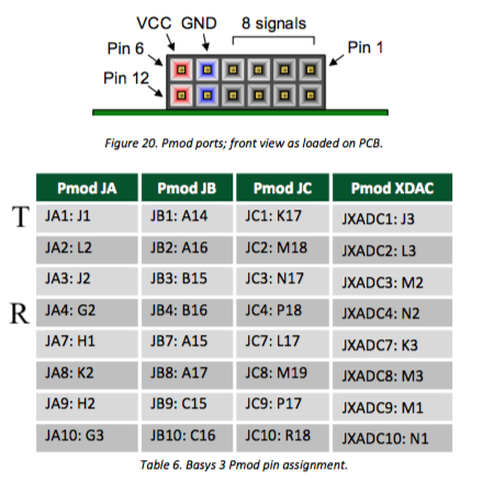
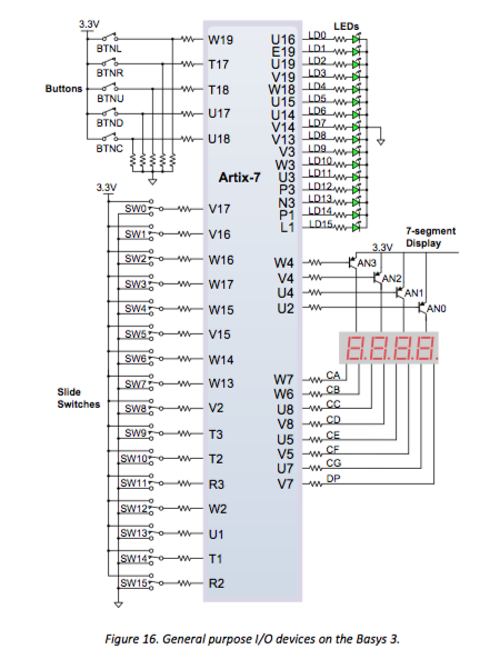
Unlike the previous FPGA/PC project, our rx and tx lines will have to come out of the PMOD blocks. You can choose any 2 lines: I will use pins 1 for tx (J1) and 4 for rx (G2) of PMOD connector JA, which is the upper left connector when looking down on the FPGA. I use these pins because they are far apart from each other, to minimize potential cross-talk although that's probably overkill. For the clock, we have to use the 100MHz W5 clock pin. For the FPGA transmit let's use BTNU (T18), the upper button, and for the system reset, let's use BTNR (T17). The bottom 8 LEDs are pins U16, E19, U19, V19, W18, U15, U14, V14, and the bottom 8 switches are V17, V16, W16, W17, W15, V15, W14, and W13. For the heartbeat output we can use LED15, which is pin L1.
So the top Verilog code will look something like this:
module top (
    input clock,
    input reset,
    input transmit,
    input [7:0] sw,
    input rx,
    output tx,
    output reg [7:0] led,
    output heartbeat,
    output [7:0] JB
);
We need to make a clock that will turn the LED heartbeat on and off at around 1Hz. Starting with a 10ns system clock, if we want to make a 10s clock signal we would need 109 counts. So let's make a 1Hz heartbeat, which means we need a counter that has 27 bits, and we will use the MSB for the heartbeat. The code would look like this:
    //
    //  make a 1Hz heartbeat signal.  starting with a 10ns clock, we will
    //  need a 27 bit counter to make a 1 sec clock, so let's use a 27 bit
    //  counter and assign the MSB to the heartbeat signal
    //
    reg [26:0] hcounter;
    always @ (posedge clock) hcounter <= hcounter + 1;
    assign heartbeat = hcounter[26];
When using push buttons on any boards, one has to always worry about "bouncing".
This was discussed in the lectures, but is basically due to the fact that when you
push a button, you are doing so on time scales that are maybe fractions of seconds,
like milliseconds. On scales shorter than that, if you picture the connection
being made, that connection might bounce. If you were to measure this, you would
find that on time scales less than around 1ms, there is usually some bouncing.
And that bouncing could easily screw up logic that is operating on 10ns time scales,
as ours is (because our clock is 100MHz). For reset push buttons, you probably don't
have to worry about bouncing so much, since all that will do is reset the state
machines and registers several times, not hurting anything. But we will be using
a push button to trigger sending data, and for THAT we don't want any bouncing!
This is easy to fix: all you have to do is to make use of a counter that counts up
when the pushed button is pushed, and resets the counter to 0 when the button is released.
When the button is bouncing, the counter will count up and keep getting reset to 0.
But when
the button settles down and (pushed), then the counter will count up to some maximum,
and when that maximum is reached, then a signal is asserted that says "ok button is
officially pushed". And when the counter gets to its maximum value, we keep it
there until the pushed button is released.
So the code is just making sure that the input button is pushed
down for some amount of time before it declares it's really pushed.
The code will look like this:
We will want a 1-shot that is high long enough for the circuit that
will be using it, which is the uart transmitter state machine (see below) to
see it. This is a general rule of programmable logic, especially when writing
code for synchronous logic: worry about the period of clocks! Let's decide
that we will want to use a 25MHz clock instead of the 100MHz clock for the
uart transmitter, which will be triggered by the 1-shot from the debouncer.
So we will want to run the debouncer at the same clock (or slower). So we
will need to generate a 25MHz clock as input to both the debouncer and
the uart transmitter. Note we could use the 100MHz system clock, but in
subsequent projects, however we will also want to look at signals on a logic
analyzer, and that means we will need an analyzer that will have to be able
to see a 100MHz clock, with a 10ns period, and that means a fancy logic
analyzer (the SALEAE we are using can go up to 500MHz but only if looking at
a few channels). So let's make the 25MHz clock, and use it as input to
the debouncer and uart, and then we can output that clock and look at things
on a logic analyzer easily.
A 25MHz clock has a period which is 4x the system 100MHz clock's 10ns period,
so all we need to do is make a 2-bit counter, and increment it with the
10ns system clock. The MSB will then have a 40ns period, as required. We
can then put the MSB into a clock buffer and use it elsewhere in the project
as the clock for the debouncer and UART.
The code will be:
Now back to the debouncer:
let's assume that after 1ms, there will be no more bouncing. Let's assume that
we will be running this debouncer with a clock that is no faster than 100MHz,
which means a 10ns period. To get to 1ms, we would have to count up to 100,000
clock ticks. To do that we would need
a counter that is 17 bits, which has a maximum value of 217 = 131072
(131072×10ns=1.31072ms).
So in the
2nd always block in the above code, if the 2nd DFF (ff2) is asserted, we start counting
("count <= count + 1"). The statement "~&count" can be confusing, so let's
take it apart. When you have a bus like "count", then "&count" means take
each bit (here there are 17) and AND them all together. If they are all 1,
then the result will be a 1, but if any of the bits are 0, then the result is
0. So "&count" = 1 when "count" is at it's maximum. The "~" means "NOT",
so the statement "if (~&count) count <= count + 1" means count up as long
as the counter has not reached it's maximum value of 1031071 (2^17-1).
The next part of the code has this: "else count <= 0;".
The "else" comes from the "if (ff2) begin" statement, so it means that the
register "ff2" is NOT pushed. So the counter is reset.
Finally, the last part says that if the counter is greater than the innput
value ticks, then we assert the output level that
the input button has indeed been pushed long enough and should be counted as pushed.
The output pulse is just a 1-shot of level, that is it goes high
when level goes high but only for 1 clock cycle.
If we use the 25MHz clock as input, then we would need the ticks input
to be 25,000.
The instantiation will be something like this:
Next we instantiate the UART transmit and receive code. We could just
copy it from another project, but I've had trouble with Vivado doing that. So to
be safe, just create 2 more source files, call them "uart_tx" and "uart_rx",
and copy the code from
uart_tx into "uart_tx" and
from
uart_rx into "uart_rx".
Now we have to instantiate these into our top level module "rpi_uart_top", and
connect the FPGA inputs and outputs.
But before we do that, let's think about what clock we want to drive them by.
Remember, the uart modules take the input clock, and an input that has "Clocks_per_Bit"
which tells it how many system clock ticks constitutes a single bit of data sent.
So if we are sending data at 1Mbps, then each bit is 1μs wide. For a system
clock of 100MHz, the number of clocks per data bit is just the ratio of the two
frequencies. The uart rx module looks at the incoming data on rx and
asserts dv when all 8 bits have been received, and if we use a 100MHz
clock to drive uart_rx, then dv will be 10ns wide. Let's slow down the
clock driving uart_rx, so that dv is wider, so that if we want to see it
on the logic analyzer (which might not run much faster than 25MHz), we can see it.
So an input clock of 25MHz might be best.
Now let's instantiate the UART receiver.
The rx code has the following inputs and outputs:
So here is how you instantiate the uart_rx reciever inside rpi_uart_top:
Next, the uart tx. The tx code has the following inputs and outputs:
The instantiation looks like this:
That's it!
The input is our "pulse" line, a 1-shot that comes out of the debouncer.
The full code should look like this:
Now we have to set up the constraints file to specify what internal variables
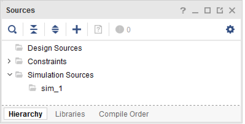
(clock, reset, tx, etc) is connected to what pins. Make a new source file by
clicking on the "+" in the "Sources" window, which looks like this:
and select "Add or create constraints":
Once you have the new file added to the project, double click on it and
go into the editor and add the constraints (click
here
for more info), using the list we've selected from above. The
code should look like this:
Debouncing
module debouncer(
    input clock,        // assume 100MHz
    input button,       // button that was pushed
    input [16:0] ticks, // number of ticks to wait before asserting level output
    output reg level,   // debounced output level, up as long as button is pushed
    output pulse    // one-shot of the level, 2 clock ticks long
    );

    //
    //  register the input button click to with the system clock.
    //
    reg ff1 = 0, ff2 = 0;
    always @ (posedge clock) begin
        ff1 <= button;
        ff2 <= ff1;
    end

    //
    //  when the input button is pushed or released, we increment or
    //  decrement a counter.   the counter has to reach a threshold
    //  before we decide that the push-button state has chnaged.
    //
    //  let's assume we have to have the button pushed for 1ms
    //  that's 100,000 clock ticks, so we will need at least 17 bits

    reg [16:0] count = 0;
    always @ (posedge clock) begin
        if (ff2) begin
            if (~&count) count <= count + 1;
        end
        else begin
            if (|count) count <= count - 1;
        end
        if (count > ticks) level <= 1;
        else level <= 0;
    end

    reg dff1 = 0, dff2 = 0;
    always @ (posedge clock) begin
            dff1 <= level;
            dff2 <= dff1;
    end
    assign pulse = level & ~dff2;

endmodule
Registers "ff1" and "ff2" will register the incoming signal ("button") so
that it's synchronous with the system clock. We use 2 DFF's to make sure that
the signal is at least 1 clock tick long. The outputs are the register
level, which goes high when the push button is pushed for enough
time (here it will be 1ms), and stays high as long as the button is pushed.
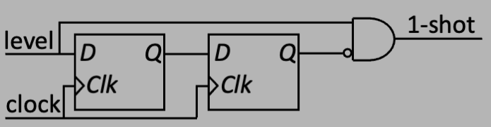
But we also might want a signal that stays high for only 1 or 2 clock cycles.
This is called a "1-shot", and is the output signal pulse. It's
formed using the signal level and a 2 clock delay of level which is
inverted and ANDed to form the 1-shot as in the following diagram:
    //
    //  make a 2 bit counter to generate a 25MHz clock for the uart tx and rx,
    //  so that we can see signals using a 25MHz logic analyzer
    //
    reg [1:0] counter;
    always @ (posedge clock)
        if (reset) counter <= 0;
        else counter <= counter + 1;
    wire clock25;
    BUFG clk1buf (.I(counter[1]), .O(clock25));
The BUFG primitive just puts the signal counter[1] onto a high speed clock line,
although the project would project run just fine without it.
    //
    //  debounce the transmit push button
    //
    wire transmit_level, transmit_pulse;
    debouncer DEBOUNCE (
        .clock(clock25),
        .button(transmit),
        .ticks(17'd25000),      // 25k x 40ns = 1ms
        .level(transmit_level),
        .pulse(transmit_pulse)
        );
UART
Connecting UART rx code
module uart_rx (
    input        i_Clocks_per_Bit,
    input        i_Clock,
    input        i_Reset,
    input        i_Rx_Serial,
    output       o_Rx_DV,
    output [7:0] o_Rx_Byte,
    output [7:0] o_debug
    );
The inputs are mostly obvious: clock, reset, and i_Rx_Serial will be tied to
the rx input to the FPGA.
The input "i_Clocks_per_bit" is telling you the baud rate, or in other words,
how wide each of the bits in the incoming data will be in number of clock ticks.
We will use a 1MHz baud rate, which means a bit width of 1μs. Given we will
use a 25MHz system clock to drive it, we then need 25 (decimal)
ticks of that clock per
tick of the incoming bit, which means "i_Clocks_per_bit" will be set to 25.
The output "o_Rx_DV" is a wire that is high when there's valid data.
This tells the "parent" code (where uart_rx is instantiated) that there's
valid data received, so go ahead and latch it. The actual data is
"o_Rx_Byte". The "o_debug" output is just for debugging, let's ignore it
for now.
    //
    //  instantiate the UART receiver
    //
    wire dv;
    wire [7:0] rx_data;
    uart_rx RECEIVER (
        .i_Clocks_per_bit('d25),
        .i_Clock(clock25),
        .i_Reset(reset),
        .i_Rx_Serial(rx),
        .o_Rx_DV(dv),
        .o_Rx_Byte(rx_data)
        );
Note that we haven't connected the "o_debug" lines to anything. That's ok,
the synthesizer will ignore it then. Also note that the outputs of uart_rx
go into wires, not registers, since they are driven from uart_rx.
Once that is done, all the top level module rpi_uart_top has to do is wait
for "dv" to be asserted, then it knows that it can latch the data. So we
do that with this code:
always @ (posedge dv) leds <= rx_data;
So "leds" will latch the data and it will stay latched until you send
something else. That's it!
Connecting UART tx code
module uart_tx (
   input        i_Clock,
   input [15:0] i_Clocks_per_Bit,
   input        i_Reset,
   input        i_Tx_DV,
   input [7:0]  i_Tx_Byte,
   output       o_Tx_Active,
   output reg   o_Tx_Serial,
   output       o_Tx_Done,
   output [7:0] o_debug
   );
The first 3 inputs are just like for uart_rx. The input "i_Tx_DV" is
the signal that there's new data to transmit out, so that will
be tied to the debounced transmit pushbutton. The output "o_Tx_Active"
is just so that if you need to know if data is being transmitted, you
could use that line. "o_TX_Serial" is tied to the FPGA "tx" signal,
and "o_Tx_Done" is a line that says the transmission is done. We won't
need "o_Tx_Active", "o_Tx_Serial", and "o_debug" here.
    //
    //  instantiate the UART transmitter
    //
    wire tx_active, tx_done;
    uart_tx TRANSMITTER (
        .i_Clocks_per_Bit('d25),
        .i_Clock(clock25),
        .i_Reset(reset),
        .i_Tx_DV(transmit_pulse),       // tied to debounced transmit
        .i_Tx_Byte(switches),   // tied to switches
        .o_Tx_Active(tx_active),
        .o_Tx_Serial(tx),       // tied to FPGA tx output
        .o_Tx_Done(tx_done)
        );
Full code
`timescale 1ns/1ps

module top (
    input clock,
    input reset,
    input transmit,
    input [7:0] sw,
    input rx,
    output tx,
    output reg [7:0] led,
    output heartbeat,
    output [7:0] JB
);
    //
    //  make a 1Hz heartbeat signal.  starting with a 10ns clock, we will
    //  need a 27 bit counter to make a 1 sec clock, so let's use a 27 bit
    //  counter and assign the MSB to the heartbeat signal
    //
    reg [26:0] hcounter;
    always @ (posedge clock) hcounter <= hcounter + 1;
    assign heartbeat = hcounter[26];
    //
    //  make a 2 bit counter to generate a 25MHz clock for the uart tx and rx,
    //  so that we can see signals using a 25MHz logic analyzer
    //
    reg [1:0] counter;
    always @ (posedge clock)
        if (reset) counter <= 0;
        else counter <= counter + 1;
    wire clock25;
    BUFG clk1buf (.I(counter[1]), .O(clock25));
    //
    //  debounce the transmit push button
    //
    wire transmit_level, transmit_pulse;
    debouncer DEBOUNCE (
        .clock(clock25),
        .button(transmit),
        .ticks(17'd25000),      // 25k x 40ns = 1ms
        .level(transmit_level),
        .pulse(transmit_pulse)
        );
    //
    //  instantiate uart_rx
    //
    wire dv;
    wire [7:0] rx_data;
    uart_rx RX (
        .i_Clock(clock25),
        .i_Clocks_per_Bit('d25),
        .i_Reset(reset),
        .i_Rx_Serial(rx),
        .o_Rx_DV(dv),
        .o_Rx_Byte(rx_data)
        );
    always @ (posedge dv) led <= rx_data;
    //
    //  instantiate uart_tx
    //
    wire active, done;
    uart_tx TX (
        .i_Clock(clock25),
        .i_Clocks_per_Bit('d25),
        .i_Tx_DV(transmit_pulse),
        .i_Reset(reset),
        .i_Tx_Byte(sw),
        .o_Tx_Active(active),
        .o_Tx_Serial(tx),       // tied to FPGA tx output
        .o_Tx_Done(done)
    );
    //
    //  for debugging
    //
    assign JB = {transmit,clock25,transmit_pulse,done,active,tx,dv,rx};
endmodule
Pins

# clock
set_property PACKAGE_PIN W5 [get_ports clock]
set_property IOSTANDARD LVCMOS33 [get_ports clock]

# reset
set_property PACKAGE_PIN T17 [get_ports reset]
set_property IOSTANDARD LVCMOS33 [get_ports reset]

# transmit
set_property PACKAGE_PIN T18 [get_ports transmit]
set_property IOSTANDARD LVCMOS33 [get_ports transmit]

# rx is pin 4 on JA
set_property PACKAGE_PIN G2 [get_ports rx]
set_property IOSTANDARD LVCMOS33 [get_ports rx]

# tx is pin 1 on JA
set_property PACKAGE_PIN J1 [get_ports tx]
set_property IOSTANDARD LVCMOS33 [get_ports tx]

# heartbeat to LED15
set_property PACKAGE_PIN L1 [get_ports heartbeat]
set_property IOSTANDARD LVCMOS33 [get_ports heartbeat]

# slide switches
set_property PACKAGE_PIN V17 [get_ports {sw[0]}]
set_property IOSTANDARD LVCMOS33 [get_ports {sw[0]}]
set_property PACKAGE_PIN V16 [get_ports {sw[1]}]
set_property IOSTANDARD LVCMOS33 [get_ports {sw[1]}]
set_property PACKAGE_PIN W16 [get_ports {sw[2]}]
set_property IOSTANDARD LVCMOS33 [get_ports {sw[2]}]
set_property PACKAGE_PIN W17 [get_ports {sw[3]}]
set_property IOSTANDARD LVCMOS33 [get_ports {sw[3]}]
set_property PACKAGE_PIN W15 [get_ports {sw[4]}]
set_property IOSTANDARD LVCMOS33 [get_ports {sw[4]}]
set_property PACKAGE_PIN V15 [get_ports {sw[5]}]
set_property IOSTANDARD LVCMOS33 [get_ports {sw[5]}]
set_property PACKAGE_PIN W14 [get_ports {sw[6]}]
set_property IOSTANDARD LVCMOS33 [get_ports {sw[6]}]
set_property PACKAGE_PIN W13 [get_ports {sw[7]}]
set_property IOSTANDARD LVCMOS33 [get_ports {sw[7]}]

# LEDs
set_property PACKAGE_PIN U16 [get_ports {led[0]}]
set_property IOSTANDARD LVCMOS33 [get_ports {led[0]}]
set_property PACKAGE_PIN E19 [get_ports {led[1]}]
set_property IOSTANDARD LVCMOS33 [get_ports {led[1]}]
set_property PACKAGE_PIN U19 [get_ports {led[2]}]
set_property IOSTANDARD LVCMOS33 [get_ports {led[2]}]
set_property PACKAGE_PIN V19 [get_ports {led[3]}]
set_property IOSTANDARD LVCMOS33 [get_ports {led[3]}]
set_property PACKAGE_PIN W18 [get_ports {led[4]}]
set_property IOSTANDARD LVCMOS33 [get_ports {led[4]}]
set_property PACKAGE_PIN U15 [get_ports {led[5]}]
set_property IOSTANDARD LVCMOS33 [get_ports {led[5]}]
set_property PACKAGE_PIN U14 [get_ports {led[6]}]
set_property IOSTANDARD LVCMOS33 [get_ports {led[6]}]
set_property PACKAGE_PIN V14 [get_ports {led[7]}]
set_property IOSTANDARD LVCMOS33 [get_ports {led[7]}]

# JB
set_property PACKAGE_PIN A14 [get_ports {JB[0]}]
set_property IOSTANDARD LVCMOS33 [get_ports {JB[0]}]
set_property PACKAGE_PIN A16 [get_ports {JB[1]}]
set_property IOSTANDARD LVCMOS33 [get_ports {JB[1]}]
set_property PACKAGE_PIN B15 [get_ports {JB[2]}]
set_property IOSTANDARD LVCMOS33 [get_ports {JB[2]}]
set_property PACKAGE_PIN B16 [get_ports {JB[3]}]
set_property IOSTANDARD LVCMOS33 [get_ports {JB[3]}]
set_property PACKAGE_PIN A15 [get_ports {JB[4]}]
set_property IOSTANDARD LVCMOS33 [get_ports {JB[4]}]
set_property PACKAGE_PIN A17 [get_ports {JB[5]}]
set_property IOSTANDARD LVCMOS33 [get_ports {JB[5]}]
set_property PACKAGE_PIN C15 [get_ports {JB[6]}]
set_property IOSTANDARD LVCMOS33 [get_ports {JB[6]}]
set_property PACKAGE_PIN C16 [get_ports {JB[7]}]
set_property IOSTANDARD LVCMOS33 [get_ports {JB[7]}]
Save the file, then run the SYNTHESIS, IMPLEMENTATION,
Generate Bitstream, and download.
The above project archive can be found
here, however unless you are sure
you have the same version of Vivado running as what was used to build it
(2023.1 if I remember right), then just rebuild it yourself to be safe.
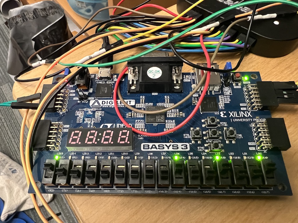
The first test we will do is called a "loopback". Just take a wire and run the output of tx into the rx input. Then set the low 8 bit switches to some pattern and hit the transmit button BTNU. You should see the output reflected on the LEDs, like this (the lowest 8 slider switches and the lowest 8 LEDs match!):
Now its time to set up the RPi to use the serial UART. The first thing to do is to understand the 40-pin GPIO header on the RPi:
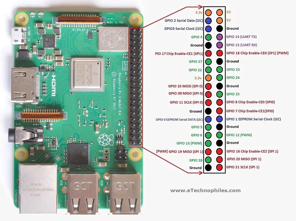
The pins on this header are connected directly to the RPi processor, and are extremely useful for doing general purpose IO as well as special purpose things like serial connections. So for the figure above, pins are numbered 1 to 40, with pin 1 being the top left pin labeled "3.3v", pin 2 being the one next to it labeled "5V", and so on: odd pins on the left top to bottom, even on the right also top to bottom. Pin 6 is labeled "Ground", pin 8 is labeled "GPIO 14 (UART TX"), and pin 10 is labeled "GPIO 15 (UART RX)". These are the pins that we are going to use for the UART transmit and receive. All we have to do is hook them up to the BASYS3 rx input and tx output, and learn how to control the UART with python. But first, let's connect pin 8 (TX) to pin 10 (RX) and use python to do a loopback test to make sure we can use the UART.
The Raspberry Pi runs a linux operating system, and all io in linux is via "ports". A port in linux is a virtual connection to some service, and you have to find the one for UART (click here for an explanation of the UART protocol and make sure you initialized the software on the RPi as prescribed here).
All ports are in the directly /dev so do a "ls -la /dev/*" to see all the ports. There are a lot of them with names like /dev/tty0 and so on. The one we want is either /dev/serial0 or /dev/serial1, probably the first one, and these are just soft links to the physical port: /dev/serial0 points to /dev/ttyS0 and /dev/serial1 points to /dev/ttyAMA0.
Python has a library that is already installed, it's called pyserial. You can check by bringing up a terminal window on the RPi and typing this (the ">" is the linux prompt, and the ">>>" is the python prompt):
> python
Python 3.9.2 (default, Feb 28 2021, 17:03:44)
[GCC 10.2.1 20210110] on linux
Type "help", "copyright", "credits" or "license" for more information.
>>> import serial
>>> exit()
When you type "python", it will load python and show you the version, which for mine (and probably for yours unless you've updated) is 3.9.2. Then at the python prompt type "import serial", and if it just comes back with ">>>" you know that the serial library is already loaded. If it's not loaded, you will have to install it by doing this:
> sudo pip install pyserial
Yes, the library to install is "pyserial" but when you import
that library into your python code, you use "import serial".
Such is life.
Now that you know pyserial is installed, it's time to write some code to exercise the UART in a loopback test, which you can do by using the following script: loopback.py
The first part of the code imports the serial library, and also sys and getopt. sys is so that you can get the command arguments, and getopt so that you can use options with the familiar linux syntax, e.g.
app -h
The next line creates a test string 'Testing 1 2 3 4' that will be sent, after which the code will do a receive and compare. After thes test string, the next bit of code implements inline options for the script: -h for help and -p for port, which should probably be /dev/serial0. So you would invoke this script on the command line by typing:
python loopback.py -p /dev/serial0
The rest of the code is a try/error block (probably overkill).
serialPort = serial.Serial(port, 115200, timeout=5)
opens a connection to the port, using baudrate 115.200 kbps, and
specifies with a timeout of 5 seconds on a UART read.
Then there are some print statements for output, followed by the line
bytes_sent = serialPort.write(test_string.encode())
That line does a write using the
test string 'Testing 1 2 3 4', bytes_sent is the number of bytes
(remember each byte has 2 characters).
The part "test_string.encode()"
will encode the string into unicode symbols (this is what pyserial
requires). Then there are 2 more print statements followed by a
UART read:
loopback = serialPort.read(bytes_sent)
where "loopback" will be the bytes read. The code then compares the
value in loopback with the encoded values in test_string and says
whether the loopback test worked, and if it did, it means you have
the right port and everything is good to go. If there's some kind of
problem with the loopback it will tell you it fails. If on the
other hand you have the wrong port, then it will just hang, and
you will have to hit control-c to exit, which is fine. So if
/dev/serial0 doesn't work, try /dev/serial1. If neither work, then
you have probably not set up the RPi os to enable serial communication,
or you have a worse problem and you can start googling to figure it out.
The full code looks like this:
import serial
import sys
import getopt

test_string = "Testing 1 2 3 4"

argv = sys.argv[1:]

opts, args = getopt.getopt(argv,"hp:")

for opt, arg in opts:
    if opt in ['-h']:
        print("\nusage: loopback -h -p ")
        print("\nwhere  is a string.  On the RPi, for UART the port is")
        print("probably going to be '/dev/serial0' or '/dev/serial1'.\n")
        print("/dev/serial0 is a soft link and is usually linked to")
        print("/dev/ttyS0.  Likewise /dev/serial1 is a soft link to /dev/ttyAMA0.\n")
        print("Here you have to include the /dev part, so best to first try")
        print("loopback -p /dev/serial0 and if that doesn't work try serial1")
        print("\nThis loopback will test by sending the string '"+test_string+"'")
        print("\nNote: if you chose the wrong port, this program might hang so you")
        print("      might have to control-c exit out of it.")
        print("\nOf course, this script assumes that you have installed pyserial!")
        exit()
    elif opt in ['-p']:
        port = arg
        print("\nTesting port "+port+" ...")

try:
    serialPort = serial.Serial(port, 115200, timeout=5)
    print("Opened port "+port+" for testing...ok")
    print("Sending '"+test_string+"' - ",end="")
    bytes_sent = serialPort.write(test_string.encode())
    print(str(bytes_sent)+" bytes sent")
    print("\nNow reading....",end="")
    loopback = serialPort.read(bytes_sent)
    if loopback == test_string.encode():
        print("received "+str(len(loopback))+" valid bytes.")
        print("--> Serial port "+port+" is working\n")
    else:
        print("receive incorrect data '"+str(loopback)+"'")
        print("--> Serial port "+port+" is NOT working!!!\n")
    serialPort.close()
except IOError:
    print("Failed at port "+port+" \n")
Before running the script, get a wire with a male and female end and connect
the RPi rx to its tx line for the loopback test.
Then run the script, and if you have the right port you should see
the following:
> python loopback.py -p /dev/serial0

Testing port /dev/serial0 ...
Opened port /dev/serial0 for testing...ok
Sending 'Testing 1 2 3 4' - 15 bytes sent

Now reading....received 15 valid bytes.
--> Serial port /dev/serial0 is working
If you have the right port but you forgot to jumper pin 8 into pin 10, you will see this:
> python loopback.py -p /dev/serial0

Testing port /dev/serial0 ...
Opened port /dev/serial0 for testing...ok
Sending 'Testing 1 2 3 4' - 15 bytes sent

Now reading....receive incorrect data 'b'''
--> Serial port /dev/serial0 is NOT working!!!
Assuming the loopback worked, now we will connect the RPi to the BASYS3 and see if we can get them to talk to each other.
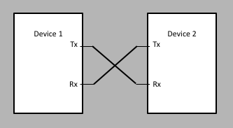
Each of these gadgets now has a rx and tx line, and now we have to connect them together. Remember that tx means from the point of view of the device that has it, so the tx of the RPi goes into the rx of the FPGA, since when the RPi is transmitting, the FPGA is receiving. The connections look like this:
First, we will connect the RPi transmitter pin to the BASYS3 receiver input, and the BASYS3 transmitter output to the RPi receiver pin. In the above instructions, we have put the FPGA tx and rx onto pins 1 and 4 of the JC pmod connector:
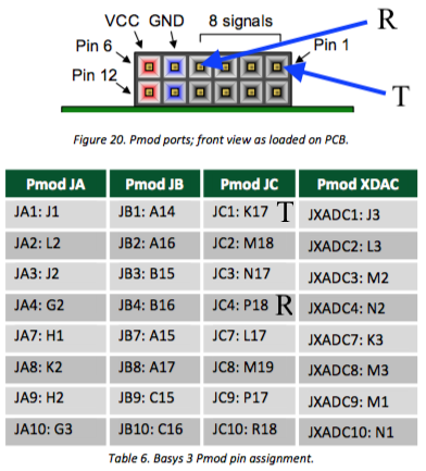
So we connect pin 1 on JC on the BASYS3 to pin 10 on the RPi, and pin 4 on JC on the BASYS3 to pin 8 on the RPi. Also, you should connect the grounds of the two boards just to be safe, so connect pin 5 or pin 11 of JC to pin 6 of the RPi (labeled "GND").
We now have to write a script that execute a UART transmit and see if the FPGA receives it ok. And, from the FPGA initiate a transmission by pushing BTNU and see if the RPi got it correctly.
A script that will do this called pyserial.py can be found here, and the code is:
import getopt
import sys
import serial

argv = sys.argv[1:]
opts, args = getopt.getopt(argv,"hr:w:b:")
operation = ""
timeout = 5
for opt, arg in opts:
    if opt in ['-h']:
        print("usage: pyserial1 -h -r  -w xxxx -b xxxx\n  -t ")
        print("-r means read  bytes")
        print("-w means write  which can be any hex value")
        print("-t to set the timeout for reading (default=5 sec)")
        exit()
    elif opt in ['-r']:
        operation = "read"
    elif opt in ['-w']:
        operation = "write"
#
#   configure serial connection
#
port = "/dev/serial0"
baud = 1000000
ser = serial.Serial(
    port,baud,timeout=5)

if ser.isOpen():
    print("Port '"+port+"' opened ok")
else:
    print("Port '"+port+"' NOT opened!  Exiting...")


if operation == "read":
    nbytes = int(arg)
    print("Reading "+str(nbytes)+" bytes...")
    r = ser.read(nbytes)
    value = hex(int.from_bytes(r,byteorder="little"))
    print("Result: '"+value+"'")
elif operation == "write":
    iarg = int(arg,16)
    if iarg > 255:
        print("Sorry, write argument is 0-255 only!")
        exit()
    print("Writing '"+hex(iarg)+"'...")
    sendb = iarg.to_bytes(1,"little")
    ser.write(sendb)
    print("1 byte sent ok!")

ser.close()
The top is just like loopback.py, setting up inline options, which are:
So in summary, to write to the FPGA and see the LEDs light up, issue the command
python pyserial.py -w a5
or any argument. If you write a5, then that's 1010 0101 binary so you should
see the corresponding LEDs light up.
To read from the FPGA, issue the command:
python pyserial.py -r 1
and then hit the transmit button (BTNL) on the FPGA and it will send a byte
made from the slide switches. Remember to do so within 5 seconds or you will
get a timeout.
The command line app works great, but these days we usually write apps that have a GUI, with options you can set by pointing and clicking etc. This can be done using the python tkinter library. The code for doing this is here and you are welcome to download it or modify it or use it to build your own. We will be using a variation of this program for our labs.