Chapter 2 - Liquefier Room
Cryomech Liquid Helium plant 22 (LHeP22)
Mobile Dewar helium Blow-off capture manifold
Chapter 5 - Liquefier Acquisition and Control Computer
Peripheral files
View website PDF document
Hi-res video: Building a helium recovery system (5 minutes long)
YouTube video: Building a helium recovery system (5 minutes long)
List of many parts with prices and links [xls]
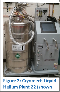 The
heart of the system is the helium liquefier plant, the Cryomech LHeP22. Some
essential information is summarized in this section, but the Cryomech manual
should be read by operators of the helium recovery system.
The
heart of the system is the helium liquefier plant, the Cryomech LHeP22. Some
essential information is summarized in this section, but the Cryomech manual
should be read by operators of the helium recovery system.
The cold head of the Cryomech utilizes pressure oscillations in a pulse tube that induces changes in entropy. A compressor is used, just like in a usual refrigeration system, raising the pressure of the refrigerant which eventually returns to the compressor at a much lower pressure. The pressurized gas travels through a rotary valve that produces an audible 2 Hz “chirping” generating gas pressure pulses. The rotary valve and pulse-tube cold-head sit atop a 150L liquid helium dewar. Pure helium gas injected into the dewar condenses on the cold surface of the cold-head and drips to the bottom of the dewar. Liquid helium accumulates in the dewar.
Very high purity helium gas is used as the refrigerant in the closed-looped system. Compressing the gas generates heat (about 10 kW) removed by chilled water. The oil in the compressor becomes too thick (just like in a normal refrigeration system) if the chilled water is too cold, which causes excessive friction and wear in the compressor. If the temperature is too high, the compressor can be damaged. A smart compressor controller measures the temperature of the compressor oil. If the oil temperature rises above 126F, the controller automatically turns off the compressor.
The liquid helium plant is also equipped with a liquid helium level gauge, dewar pressure gauge, and thermometers that measures the temperature of the cold-head, helium gas used as a refrigerant, and the input and output chilled water. A heater cartridge hangs off of the cold head and rests on the bottom of the dewar. An onboard computer reads and logs all sensor data while controlling the compressor, cold head, and heater.
The control software offers two automatic modes. The first is the “auto on/off” mode. In this mode, the dewar pressure is maintained between 0.5 and 8 PSIG. The natural boil-off of liquid helium raises the pressure in the dewar. When the pressure reaches 8 PSIG, the compressor turns on and the cold-head begins condensing helium gas reducing the dewar pressure. When the pressure reaches 0.5 PSIG, the compressor is turned off. The “auto-continuous” mode maintains the dewar pressure at 0.75 PSI by continuously running the compressor and regulating the power to the dewar heater.
A dewar vent port with an inline 10 PSI relief valve exhausts into the recovery bladder. Two catastrophic relief valves that vent to the room are set at 15 PSIG. If the dewar pressure falls below 0.25 PSIG, power is supplied to the dewar heater maintaining a pressure above atmosphere. Note that the heater controller must be manually disabled when no liquid is present in the dewar. Otherwise, the dewar insulation may be damaged.
The user supplies purified helium gas at the input of the LHeP22. A pressure regulator prevents the flow of gas into the dewar unless the pressure is greater than around 3 PSIG. The gas must be greater than 99.99% pure to prevent icing of the cold head. Ice forms an insulating layer which diminishes heat transfer to the helium gas degrading liquefaction rates.
If icing occurs, the entire 150L dewar must be warmed up to regenerate the cold head. The process takes about 10 days to warm to room temperature. To regenerate, evacuate the dewar and backfill with pure helium. Once the system is restarted, accumulation of liquid helium in the dewar requires 40 hours. The maximum measured liquefaction rate for our unit is 26.3 LLHe/day.
Modifications to the LHeP22 include relocating the chilled water ports to the back-side of the unit, connecting a dewar exhaust port and 10 PSIG relief valve to the recovery system, and reorienting the helium gas input to the back of the unit.
Special note: To gain access to a hidden settings menu, press the “O” and “H” in the Cryomech logo on the screen of the onboard computer.
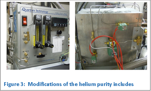 The
helium purity meter is made by Quantum Technology. The meter utilizes a pair of
hot wire anemometers. The idea is that various types of gasses have different
thermal conductivities. Compared to the main constituents of air, helium has a
much higher thermal conductivity. The level of air impurity changes the heat
loading of the hot wire. Since the resistance of the wire is temperature
dependent, a signal is generated based on impurity level. To gain sensitivity, the
hot-wires in two identical chambers are measured in a bridge configuration. A
trim-pot on the front panel is used to balance the bridge. Adjusting the
trim-pot with the same pure reference gas flowing across both anemometers
zeroes the meter. Once zeroed, a sample gas is then routed through one of the anemometer
chambers and compared with the reference gas chamber.
The
helium purity meter is made by Quantum Technology. The meter utilizes a pair of
hot wire anemometers. The idea is that various types of gasses have different
thermal conductivities. Compared to the main constituents of air, helium has a
much higher thermal conductivity. The level of air impurity changes the heat
loading of the hot wire. Since the resistance of the wire is temperature
dependent, a signal is generated based on impurity level. To gain sensitivity, the
hot-wires in two identical chambers are measured in a bridge configuration. A
trim-pot on the front panel is used to balance the bridge. Adjusting the
trim-pot with the same pure reference gas flowing across both anemometers
zeroes the meter. Once zeroed, a sample gas is then routed through one of the anemometer
chambers and compared with the reference gas chamber.
In order to accurately measure purity level to 99.99%, the hot wires need a short time to thermally stabilize and the helium lines must be sufficiently purged. Also, flow rates should be the same through the two chambers adjusted by the valves at the bottom of the front panel rotometers (see Appendix 3 for calibration charts). The gas purifiers produce pure helium gas over many days, but the purity level degrades quickly over several hours as the adsorbent bed in the cold-trap reaches “break-through”, the point at which the final layer of the adsorbent bed begins to saturate.
The meter analog output voltage is measured by computer. Calibration of voltage output to impurity level was performed (see Appendix 2). The computer controls the gas flow through the anemometers via
two 2-way and one 3-way solenoid valves that are mounted to an aluminum plate on the back of the meter.
Special Notes: A much better meter became available after purchase. I would recommend the acoustic purity meter made by Stanford Research instead. They have an application note on the operation of the meter in helium recovery system at my request during the construction of the IREAP helium recovery system.
A Gast MAA-P102-MB diaphragm pump is used to draw the helium from the bladder (very near 0 PSIG) and pressurize upstream components. The diaphragm pump produces much larger flow rates and pressures than necessary. Upstream 10 and 15 PSI pressure relief valves prevent over pressurization of upstream components.
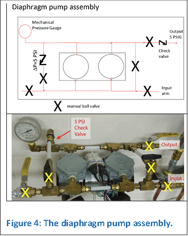
One motor actuates two diaphragms that pump in parallel. An in-line check valve locks the pressure differential between the output and input to 5 PSI. The diaphragms permanently deform if left under vacuum or pressure for long durations, and leads to premature failure (and leaking). When the pump is off, the bypass valve is opened to equalize the pressure to atmosphere on both sides of the diaphragm.
A low-pressure check valve at the output of the diaphragm pump ensures that the cold trap and water trap stay under pressure when the pump is turned off.
The diaphragms are rated for 6 months of continuous use. I replace them every 3 months in order to minimize the possibility of cracked/leaking diaphragms pumping large amounts of helium into the room. Instructions and torque specifications for replacing the diaphragms are provided by Gast. Do not squeeze the diaphragms too tightly to the aluminum housing.
The diaphragms should be periodically leaked checked. Two tests should be performed, a static and dynamic leak test. Statically pressurize the input and output ports to about 10 PSI and close the input and output valves. Watch for a reduction of pressure. A Dynamic leak test involves running the pump with the output valve closed while applying a few PSIG to the input of the pump (the output is 5 PSI higher). The input valve of the pump is then closed and the pressure monitored.
A few different types of NPT sealants were used during assembly. XPando is the black, concrete-like substance that is a permanent connection. Yellow (high density and high purity) teflon tape is used on some connection. Locktite pipe dope is used. A special surface adhesion layer made by Loctite was pre-applied to the aluminum pump housing.
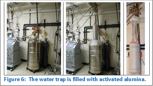
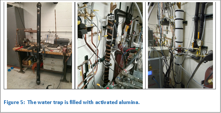 The
helium from the bladder and diaphragm pump is routed through a custom-made
water trap. The trap is filled with beads of activated alumina. Indicating
activated alumina is packed into windows along the length of the trap. The trap
is conveniently regenerated in situ by heating and flowing air across
the bed.
The
helium from the bladder and diaphragm pump is routed through a custom-made
water trap. The trap is filled with beads of activated alumina. Indicating
activated alumina is packed into windows along the length of the trap. The trap
is conveniently regenerated in situ by heating and flowing air across
the bed.
Without the water trap, excessive amounts of water are adsorbed in the cold trap. This is a problem for two reasons. Dangerous ice plugs form that block the flow of helium. Also, the zeolites in the adsorbing bed strongly trap dipolar water at the expense of trapping other impurity gasses. A bake temperature of 300C is necessary to drive off the water, so the zeolites must be removed from the cold-trap vessel. A much lower regeneration temperature is required to release trapped oxygen and nitrogen and can therefore be performed in situ.
End plates and NPT nubs for mounting windows was TIG welded to a 6ft long 3” diameter black steel pipe. Two 1” NPT Wye 150 mesh filters on either end retain the beads. The water trap is filled with about 15 lbs of F-200 activated alumina with an estimated net capacity of 1.3L of water at a relative humidity of 20% (see Appendix 1). Five window housings located along the length of the trap are packed with blue indicating activated alumina, where blue indicates dry and white indicates water saturation, permitting visual monitoring of the adsorbing bed.
It is estimated with an air impurity level of 1% and a volumetric flow rate corresponding to the maximum liquefaction rate (~25LLHe/day), the water trap will saturate in 1.5-2 weeks. Experimentally, I have run the trap for 1.5 weeks in high-humidity conditions (summer time) with the trap approximately 4/5 saturated at a continuous flow of 25 LLhe/day.
The activated alumina is regenerated by baking and supplying a counterflow of either air or dry N2 gas. Two 720W, 10’ long and 1” wide, silicone heater tapes with attached regulating thermostats are wrapped around the 3” diameter pipe held with Kapton tape. The silicone heaters are rated to 233C, and effective regeneration temperatures is 150C. Four K-type thermocouples measure the pipe and heater tape temperature. The pipe and heater tape are wrapped in 1” thick high-temperature glass-fiber insulation. The heaters are currently tuned so that the required temperature range is automatically maintained.
Counterflow of N2 gas is supplied by the 240L nitrogen dewar gas-vent port. The flow direction should be opposite that of the usual helium gas flow. The trap is regenerated when all the beads are blue and no liquid water is visible in the hose connected to the output located at the top of the water trap. The water trap can be regenerated in about 12 hours with a flow rate of 14 CFH of nitrogen (as measured by an argon rotometer). I usually evacuate the hot adsorbing bed immediately after turning the heaters off and backfill with industrial grade helium. The trap requires about 5 hours to cool to room temperature.
An alternative is to use a squirrel-cage blower to force room air backwards through the adsorbing bed after the beads are heated. I have used the method instead of the nitrogen, and it seems to work well.
 The
cold trap is made by Quantum Technology. A stainless steel vessel with an
adsorbing bed of zeolites is lowered into a dewar and submerged in liquid
nitrogen. Incoming dry helium flows through the cold zeolites bed removing impurities
like nitrogen and oxygen. An output helium purity of 99.99% is attained.
The
cold trap is made by Quantum Technology. A stainless steel vessel with an
adsorbing bed of zeolites is lowered into a dewar and submerged in liquid
nitrogen. Incoming dry helium flows through the cold zeolites bed removing impurities
like nitrogen and oxygen. An output helium purity of 99.99% is attained.
The input line routes gas from the top of the cold trap down through a 1” diameter pipe to near the bottom of the cold trap. A cup at the bottom of the pipe collects any water that accumulates (from ice that sticks to the walls of the pipe and, upon warmup, runs down to the bottom of the tube and into the cup). A smaller concentric tube runs from the bottom of the cup to the top of the trap. Any accumulated water is purged through this tube by pressurizing the trap. Since implementing the water trap, no water accumulates in the cold trap. I assume there are perforations in the 1” pipe near the bottom with a mesh screen. Adsorbing zeolite beads fill the 9” diameter section of the trap. Helium flows from the bottom to the top of the adsorbing bed. The 4” diameter neck section is the heat exchanger. The output port includes a 10 PSI relief valve.
The entire cold trap is lowered into a 240L cryofab nitrogen dewar with a 9.25” diameter neck. Always maintain a trap pressure above atmosphere during cooling. The adsorbing bed requires about 1.5 hours to chill.
Qantum Technology specifies that the trap capacity is about 1-1.5 kg of dry air, which translates into 9 days of continuous flow at 22 LLHe/day and a 99% purity level. The heat exchanger in the neck is a poor design, and the mass of the trap is inappropriately large causing copious amounts of LN boil-off upon cooling from room temperature as well as excessive warm-up times when regenerating the trap. No flange on the cryostat requires the trap be continuously hung from a crane.
Since I originally had no water trap, I have twice poured out the beads from the “output” port and baked the zeolites at 300C in an external oven. To replace the beads, suction on the “input” port using a shop vacuum draws a vacuum inside the vessel, which suctions the beads into the trap via the “out” port. There are explicit instructions on how to do this from Quantum Technology. The hoses and fittings for this procedure are stored in the liquefier room.
LN AutoRefill system:
 The
cold-trap was outfitted with an autorefill system. The level should be
maintained very near the bottom of the 4” diameter neck. An American Magnetics
LN-Level capacitiance sensor attaches to the controller. Set points A and B
define the high and low LN levels. When the LN level reaches set point B, the onboard
relay energizes and powers an external cryogenic solenoid allowing flow from a
pressurized 240L mobile LN dewar. When the cold trap reaches set point A, the controller
shuts off the flow. Set points “High” and “Low” are points that, when breached,
trigger a fault mode where the controller no longer automatically acts. A
maximum time interval can be set for the refill process (to go from level B to
A). If the time interval is exceeded, then the flow is stopped and fault mode
is triggered. This is an extra safety feature preventing accidental
overfilling.
The
cold-trap was outfitted with an autorefill system. The level should be
maintained very near the bottom of the 4” diameter neck. An American Magnetics
LN-Level capacitiance sensor attaches to the controller. Set points A and B
define the high and low LN levels. When the LN level reaches set point B, the onboard
relay energizes and powers an external cryogenic solenoid allowing flow from a
pressurized 240L mobile LN dewar. When the cold trap reaches set point A, the controller
shuts off the flow. Set points “High” and “Low” are points that, when breached,
trigger a fault mode where the controller no longer automatically acts. A
maximum time interval can be set for the refill process (to go from level B to
A). If the time interval is exceeded, then the flow is stopped and fault mode
is triggered. This is an extra safety feature preventing accidental
overfilling.
The capacitance level gauge is a pair of concentric fragile thin-walled stainless steel tubes. The cold trap is suspended at two points by a hoist. The expensive and fragile level gauge slides between the cold trap and dewar neck and can easily become bent or dented if the cold trap is bumped. Also, pressure equalization holes in the outer tube of the gauge is located outside the dewar causing water to cryopump between the tubes. The capacitance therefore changed and the level readings failed. Furthermore, removal of the capacitance gauge from LN caused icing inside and outside the level gauge. It therefore had to be thoroughly dried before re-inserting into the LN dewar. To solve these problems I placed the fragile capacitance gauge inside a thicker-walled stainless steel tube (shown in Figure 7), sealed the upper end of the gauge inside the tube, and drilled pressure equalizing holes so that they now reside inside the cold trap dewar just above the LN level. Upon removing the assembly from LN, a conical-shaped tube with o-rings is inserted into the outer armored sheeth. Dry nitrogen gas flows through the assembly and out the pressure equalization holes preventing ice and water from contaminating the capacitance gauge.
A transfer line was built onto the cold trap. It consists of a JIC fitting, a 2-way cryogenic solenoid valve, a bracket, a gas diffuser, and a thick copper-foil liquid-deflection shield that prevents asymmetrically cooling of the trap during LN transfers. The solenoid valve is actuated by the American Magnetics controller and a computer reads the LN level from the RS-232 serial port.
An electric hoist and custom-built crane maneuver the cold trap into the 240L 9” wide-mouth LN dewar. The steel crane was MIG welded together. The hoist can cause terrible damage if not carefully used. Care must be taken not to damage the crane’s aluminum pulley by running steel cable clamps into it. A dead-man’s switch at the hoist housing to prevents catastrophic collision of the cold trap with the ceiling. Before hoisting the cold trap out of the dewar, it is imperative that the liquid nitrogen transfer line and the transfer solenoid power cable are disconnected, and the capacitance LN level gauge is removed. The gauge could be crushed between the dewar and cold trap, damaging both. While raising and lowering the trap into and out of the dewar, careful alignment of the cold trap and dewar mouth is necessary to prevent damaging the dewar opening.
New adsorbing bed:
The adsorbing bed is spherical beads of zeolite that are approximately 2.3 mm in diameter. I ordered acid-washed coconut-shell activated charcoal with a mesh size 4x8 as a possible replacement. Liquid water causes zeolites to disintegrate, and removal of water vapor requires bake temperatures of 300C. For activated carbon, the bake temperature is 150F and are not damaged from water exposure. The regeneration should therefore be quicker and easier to fully regenerate, The performance and capacity to adsorb nitrogen and oxygen is very similar at LN temperatures.
Styrofoam Lid:
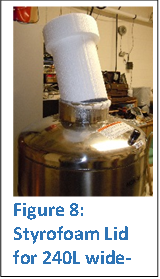 No
lid to the wide-mouth LN dewar was provided. A 4x4x2’ brick of polystyrene (a
$20 archer’s target) was cut using a home-made bow strung with NiCr wire. The
wire was heated with a variac. The Styrofoam was rough cut and then placed on a
plate with a screw that pierced the Styrofoam providing a rotation axis. The
piece was spun about the point as the NiCr sliced through it. Two cylinders
were cut and then glued together to make a tight fitting polystyrene lid.
No
lid to the wide-mouth LN dewar was provided. A 4x4x2’ brick of polystyrene (a
$20 archer’s target) was cut using a home-made bow strung with NiCr wire. The
wire was heated with a variac. The Styrofoam was rough cut and then placed on a
plate with a screw that pierced the Styrofoam providing a rotation axis. The
piece was spun about the point as the NiCr sliced through it. Two cylinders
were cut and then glued together to make a tight fitting polystyrene lid.
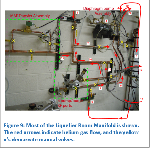 Figure
9 shows most of the mechanical room manifold. The yellow x’s mark the location
of manual ball valves. Red arrows indicate the path of the helium gas flow.
The usual gas flow is sequential numbered 1 through 12. Helium arrives at the
manifold (1) from the bladder, and is routed (2) to the diaphragm pump assembly
(3). The pump assembly draws helium from the bladder and pressurizes the
upstream components to around 5 PSIG. From the pump assembly, the helium flows
through a check valve (4). The check valve maintains the upstream components
above atmospheric pressure even when the pump is off. The helium then flows
through a flexible corrugated hose, and to the top of the water trap.
Figure
9 shows most of the mechanical room manifold. The yellow x’s mark the location
of manual ball valves. Red arrows indicate the path of the helium gas flow.
The usual gas flow is sequential numbered 1 through 12. Helium arrives at the
manifold (1) from the bladder, and is routed (2) to the diaphragm pump assembly
(3). The pump assembly draws helium from the bladder and pressurizes the
upstream components to around 5 PSIG. From the pump assembly, the helium flows
through a check valve (4). The check valve maintains the upstream components
above atmospheric pressure even when the pump is off. The helium then flows
through a flexible corrugated hose, and to the top of the water trap.
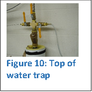 At
the top of the water trap are three manual ball valves as shown in Figure 10.
Opening the left ball valve directs the flow to the helium purity meter. The
right ball valve vents to the room. The flow traverses through the water trap
(5), past the water trap relief valve (6), through the copper pipes (7 and 8),
and sent into a corrugated stainless steel hose (9) and into the cold trap. The
purified gas is returned from the cold trap (10) and routed through the copper
manifold (11) and into another corrugated stainless steel hose that attaches to
the input of the liquefier (12).
At
the top of the water trap are three manual ball valves as shown in Figure 10.
Opening the left ball valve directs the flow to the helium purity meter. The
right ball valve vents to the room. The flow traverses through the water trap
(5), past the water trap relief valve (6), through the copper pipes (7 and 8),
and sent into a corrugated stainless steel hose (9) and into the cold trap. The
purified gas is returned from the cold trap (10) and routed through the copper
manifold (11) and into another corrugated stainless steel hose that attaches to
the input of the liquefier (12).
As shown in Figure 11(a), the helium passes through the liquefier solenoid valve, pressure regulator, and into the liquefier 150L dewar. A tee at the input diverts some of the flow into the helium purity meter. Also shown in Figure 11(a) is the attachement from the mobile dewars that vent directly into the 150L dewar that will be discussed in the next section.
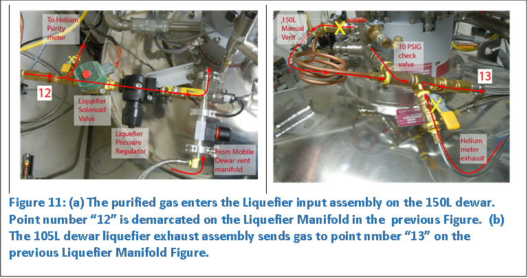 Figure
11(b) shows two venting ports from the 150 L dewar that exhaust into the
liquefier manifold (13). One is a manually operated ball valve, and the other
is an inline 10 PSI check valve. The helium exhaust from the helium purity
meter is also merged into the exhaust line. The combined exhaust is routed into
a corrugated stainless steel hose, into the manifold (14), and then to the bladder
(1).
Figure
11(b) shows two venting ports from the 150 L dewar that exhaust into the
liquefier manifold (13). One is a manually operated ball valve, and the other
is an inline 10 PSI check valve. The helium exhaust from the helium purity
meter is also merged into the exhaust line. The combined exhaust is routed into
a corrugated stainless steel hose, into the manifold (14), and then to the bladder
(1).
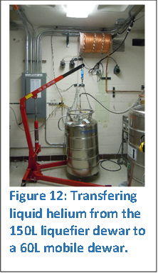 Also
shown in Figure 9 is the MAF Transfer Assembly. Helium exhaust gas from mobile dewars
during a liquid transfer, as shown in Figure 12, is heated to room temperature.
A copper coil with three 900W heater-tapes with variacs are wrapped around
several loops. The gas then travels into the MAF Transfer Assembly, which can
be routed through the transfer solenoid and helium MAF sensor (see Section Helium
gas Mass Flow meters). The sensor measures the gas flow rate used to
control the rate of liquid transfer. Another useful parameter is the liquid
level in the dewar which is derived from the dewar weight during transfer. In
the adjoining picture, the weight is measured by suspending the dewar from an
engine hoist with a hanging scale. A platform scale with an RS-232 has recently
replaced this scale allowing transfers to be automatically shut off by a
computer based on weight, time of transfer, or temperature of the MAF sensor
(see Section Liquid Helium dewar-to-dewar transfer shut-off interlock
for details). The exhaust gas from dewar-to-dewar transfers is routed (15) back
into the bladder (1).
Also
shown in Figure 9 is the MAF Transfer Assembly. Helium exhaust gas from mobile dewars
during a liquid transfer, as shown in Figure 12, is heated to room temperature.
A copper coil with three 900W heater-tapes with variacs are wrapped around
several loops. The gas then travels into the MAF Transfer Assembly, which can
be routed through the transfer solenoid and helium MAF sensor (see Section Helium
gas Mass Flow meters). The sensor measures the gas flow rate used to
control the rate of liquid transfer. Another useful parameter is the liquid
level in the dewar which is derived from the dewar weight during transfer. In
the adjoining picture, the weight is measured by suspending the dewar from an
engine hoist with a hanging scale. A platform scale with an RS-232 has recently
replaced this scale allowing transfers to be automatically shut off by a
computer based on weight, time of transfer, or temperature of the MAF sensor
(see Section Liquid Helium dewar-to-dewar transfer shut-off interlock
for details). The exhaust gas from dewar-to-dewar transfers is routed (15) back
into the bladder (1).
The four pump/purge ports on the Liquefier manifold provide great flexibility to perform a variety of tasks at one easily accessible location. The water trap and cold trap are independently isolated with ball valves, independently regenerated with backflow of nitrogen or air (by attaching a squirrel cage motor to the KF flange), evacuated with a pump station, and backfilled with helium. All pipelines in the manifold are pumped and purged. The pipelines between the diaphragm pump and liquefier can also be flushed with gas from the bladder by running the diaphragm pump, or the gas from the bladder can be continuously purified without liquefying. The cold trap can be maintained under pressure while cold for long periods of time by pressurizing with helium from a cylinder. The diapharagm pump is easily leak checked (see Section Diaphragm pump assembly) by closing appropriate valves and attaching a pressure sensitive pressure gauge and pressurizing cylinder to the manifold.
One of the mobile helium dewar exhaust ports consists of a ball
valve, an in-line 0.5 PSI check valve, and Swagelok B-QC4 brass quicklock
connectors (Figure 13a). The exhaust flows into Mobile Dewar Blow-off Capture Manifold
via a ¼” corrugated stainless steel flex hose. The manifold 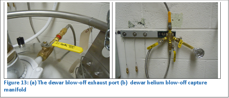 connects
to the Liquefier 150L dewar as shown in Figure 11(a). A KF port is also
included on the manifold for pumping and purging. Two dewars simultaneously
connect to the blow-off manifold.
connects
to the Liquefier 150L dewar as shown in Figure 11(a). A KF port is also
included on the manifold for pumping and purging. Two dewars simultaneously
connect to the blow-off manifold.
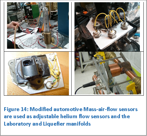 An
automotive mass air flow (MAF) sensor was modified for use as a helium mass
flow sensor. The sensor is a hot wire anemometer with onboard electronics that
maintains the hot wire at constant power. The lid was replaced with an aluminum
plate to attach three BNC connectors to apply 12 Vdc, and read the signal
voltage as well as an RTD thermometer. An oring gland was modified to adequately
seal between the plastic housing and a copper fittings that is part of a brazed
housing. The o-ring seal slowly leaks due to imperfections in the plastic. The
leaks are insignifcant for short duration like for transfers. The meters have
accompanying isolation valves on both the Lab and Liquefier Room Manifolds. The
sensitivity of the meter is adjusted by rotating the meter to different angles inside
the copper housing. An LED display shows the voltage that relates to flow rate.
Calibration of the meter voltage to a volumetric flow rate (CFH) of helium is
given in Appendix 2, and wiring charts are provided in Appendix 8.
An
automotive mass air flow (MAF) sensor was modified for use as a helium mass
flow sensor. The sensor is a hot wire anemometer with onboard electronics that
maintains the hot wire at constant power. The lid was replaced with an aluminum
plate to attach three BNC connectors to apply 12 Vdc, and read the signal
voltage as well as an RTD thermometer. An oring gland was modified to adequately
seal between the plastic housing and a copper fittings that is part of a brazed
housing. The o-ring seal slowly leaks due to imperfections in the plastic. The
leaks are insignifcant for short duration like for transfers. The meters have
accompanying isolation valves on both the Lab and Liquefier Room Manifolds. The
sensitivity of the meter is adjusted by rotating the meter to different angles inside
the copper housing. An LED display shows the voltage that relates to flow rate.
Calibration of the meter voltage to a volumetric flow rate (CFH) of helium is
given in Appendix 2, and wiring charts are provided in Appendix 8.
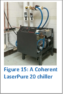 A
closed-cycle chiller, a Coherent LaserPure 20, removes heat from the compressor
of the LHeP22. A heat exchanger in the LaserPure unit transfers the heat from
the closed-cycle coolant to the building chilled water system. The cooling
power is adjustable: a coolant-reservoir bulb thermometer actuates a bypass diaphragm
valve that is adjustable. This allows some tuning of the coolant temperature.
A
closed-cycle chiller, a Coherent LaserPure 20, removes heat from the compressor
of the LHeP22. A heat exchanger in the LaserPure unit transfers the heat from
the closed-cycle coolant to the building chilled water system. The cooling
power is adjustable: a coolant-reservoir bulb thermometer actuates a bypass diaphragm
valve that is adjustable. This allows some tuning of the coolant temperature.
The total capacity of the chilled water lines and reservoir is 7.8 gallons. Every inch of coolant level in the reservoir corresponds to ½ gallons. The coolant is a mixture of pure water with 25% BioFrost (by volume), polypropylene glycol with corrosion inhibitors.
The front panel power switch is a low-voltage circuit, which has been wired in parallel with a computer controlled relay. The chiller is automatically turned off if the coolant temperature rises above a user defined set point preventing the water pump from overheating.
A stand was welded together to raise the chiller off the ground for easy draining.
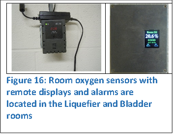 The
room oxygen levels in the Liquefier and Bladder Rooms are separately monitored
by Macurco OX-6 Oxygen detectors. Each wall mounted unit is powered by a 12V
power supply and includes a digital readout of the oxygen concentration, a
4-20mA oxygen sensor output, two alarm relays with programmable set points, and
an internal buzzer.
The
room oxygen levels in the Liquefier and Bladder Rooms are separately monitored
by Macurco OX-6 Oxygen detectors. Each wall mounted unit is powered by a 12V
power supply and includes a digital readout of the oxygen concentration, a
4-20mA oxygen sensor output, two alarm relays with programmable set points, and
an internal buzzer.
The Department of Environmental Safety at UMD required remote oxygen level displays as well as audible and visual alarms exterior to the two rooms. An Arduino Uno controls a 1.8" Color TFT LCD display ST7735 (a wiring diagram is provided in Appendix 9), and homebrewed software uploaded to the Arduino Uno. Custom 12Vdc remote buzzers and flashing-light alarms were also implemented.
The flashing lights are connected to the ALARM relay with an oxygen concentration set point of 19.5%. Buzzers are connected to the FAN relay with a set point of 18%. Lifetime of the oxygen sensor is rated between 2 and 3 years. Calibration of the sensor is recommended at 2 years.
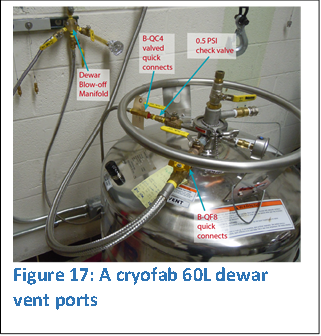 Three
mobile helium dewars are used in the recovery system: a new Cryofab 60L dewar,
a Cryofab refurbished 100L dewar, and an older 100L dewar that came from IBM and
manufactured in the early 1980’s. Each dewar is outfitted with a Swagelok quick
connect (B-QC4) with an
inline 0.5 PSIG pressure relief valve. The Swagelok connectors are valves on both
the male and female ends. The valves seal shut disconnected, and open when
connected. The male connectors are on the dewars with protective caps. The
interface with the lab manifolds is simple, quick, and foolproof.
Three
mobile helium dewars are used in the recovery system: a new Cryofab 60L dewar,
a Cryofab refurbished 100L dewar, and an older 100L dewar that came from IBM and
manufactured in the early 1980’s. Each dewar is outfitted with a Swagelok quick
connect (B-QC4) with an
inline 0.5 PSIG pressure relief valve. The Swagelok connectors are valves on both
the male and female ends. The valves seal shut disconnected, and open when
connected. The male connectors are on the dewars with protective caps. The
interface with the lab manifolds is simple, quick, and foolproof.
A Swagelok high flow quick connect (B-QF8) is located on each dewar on a separate vent port. This provides a convenient way to connect/disconnect to pressurize or vent the dewar during LHeP22 liquid helium transfers.
 All
liquid helium and nitrogen dewars are weighed to measure the liquid level (see
Appendix 4). An engine hoist with a hanging scale lifts dewars.
All
liquid helium and nitrogen dewars are weighed to measure the liquid level (see
Appendix 4). An engine hoist with a hanging scale lifts dewars.
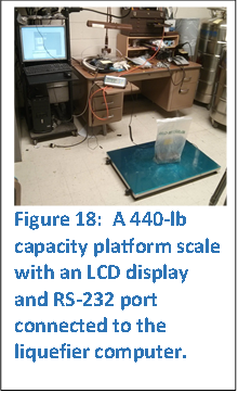
Recently, a platform scale with an RS-232 connection has been added to measure the liquid level of the mobile helium dewars during liquid transfers. The weight is graphed in real time on a computer. When the weight of the liquid reaches a user defined set-point, the transfer is automatically shut off.
Next: Chapter 3 - Bladder Room