 |
Alternative Homework Assignment: Tuning a Radio |
Lucy is driving along a highway listening to her car radio when the station she is listening to begins to fade in and out forcing Lucy to tune in a new station. As she turns the knob on the radio, many different stations become tuned in and then fade out, and Lucy begins to wonder exactly how turning the knob allows the radio to distinguish one station from another. Thinking more about her radio, Lucy begins to wonder how it works aside from selecting a station. In short she wonders how it turns radio waves into sound waves. In solving this problem, you will use a radio and your knowledge of AC circuits to answer Lucy's questions.
| Part I:
a) When radio waves interact with a radio's antenna, they induce a current in the antenna which results in an EMF across the radio's tuner. Each radio station broadcasts radio waves of a particular frequency. How does the frequency of the induced EMF compare to the frequency of the radio waves? b) Get a radio and turn in on. The radio you have before you is receiving radio waves from many different sources. The radio waves from every local radio station, not to mention television stations, radio phones, and many other sources of radio waves are causing the antenna on your radio to generate a complicated EMF made up of many different frequencies all corresponding to the different sources. The tuner's task is to seperate one of these signals out from the others and amplify it. One way of accomplishing this is by using a series RCL circuit. To begin to see how this works, write an expression for the impedance of an RCL circuit as a function of frequency. R,C, and L will be parameters of this expression. c) Find the frequency that minimizes the impedance in this circuit. This state of minimal impedance is called resonance. d) Choose values of R, C, and L that are reasonable real world values, and for which the frequency that minimizes the impedance is one of your favorite radio station's frequency. e) Now find the four radio stations that are most nearly adjacent to the station you used in the question above. Record the frequencies of these stations. f) Calculate the impedance in the circuit you have designed at each of these frequencies. g) In order to easily supress the other signals, the impedance for the resonant frequency should be one tenth that of the next smallest impedance you calculated. If this is not the case, change your values of R, C, and L until your circuit meets this requirement. |

|
Part II:
a) Now consider changing the station. In order to do this you must change the resonant frequency. Change the capicitance of your circuit so that it tunes in a different station and check to see if the impedence at adjacent stations' frequencies is large enough to supress these stations' signals.
b) Would the effect have been different if you had changed the inductance of the circuit rather than the capacitance? If so, how?
c) If a variable capacitor is used to change the station, what range of capacitance must this capacitor have in order to reach the entire A.M. dial? How about the F.M. dial?
| Part III:
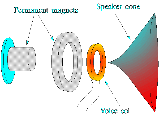
a) Once a particular broadcast has been seperated from the other radio sources, the radio must read the information that is contained in the signal and translate this into a series of electrical impulses that are to sent to the speaker in order to changed to sound. The exact method for doing this is beyond the scope of this problem, but we can look at how the speaker changes these impulses into sound. The components of a loudspeaker are shown disassembled in the figure to the right. A pair of permanent magnets create a magnetic field that exerts forces on the current in the voice coil. The voice coil is attached to the speaker cone and the magnetic forces cause the cone to vibrate in a way that matches the vibrations of current in the voice coil. What is the net force on a current loop in a uniform magnetic field? b) The magnetic force on the voice coil arises because the magnetic field at the coil is not uniform. Suppose a voice coil in a loudspeaker has 40 turns of wire and a diameter of 1.8 cm, and the current in the coil is 0.8 A. Assume the magnetic field at each point of the wire of the coil has a constant magnitude of 0.2 T and is directed at an angle of 60º outward from the normal to the plane of the coil. Let the axis of the coil be the y direction. The current in the coil is in the direction shown in the figure below (counterclockwise as viewed from a point above the coil on the y-axis). Calculate the magnitude and direction of the resultant magnetic force on the coil. c) Explain how this system converts electric impulses to sound waves. | 
|
 |
Work supported in part by NSF grant DUE-9455561 |
These problem written and collected by K. Vick, E. Redish, and P. Cooney. These problems may be freely used in classrooms. They may be copied and cited in published work if the Activity-Based Physics (ABP) Alternative Homework Assignments (AHA's) Problem sight is mentioned and the URL given.
To contribute problems to this site, send them to redish@quark.umd.edu.
 |
Go back to the AHA page |
Maintained by
University of Maryland PERG
Comments and questions may be directed to
E. F. Redish
Last modified June 25, 2002