In this project, we will connect push buttons, leds, RGB leds, and switches, build a project, and learn to use it in python using PYNQ.
Board Files
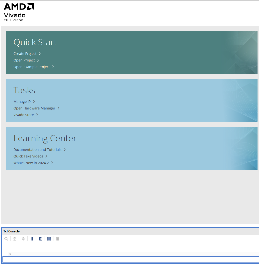
To use Vivado, you have to first have the board files that have the parts for the 4x2. You can download them from here, then unzip and store it some place convenient. Then run Vivado, you should see this screen:
set_param board.repoPaths <path>
xhub::refresh_catalog [xhub::get_xstores xilinx_board_store]
Project Creation
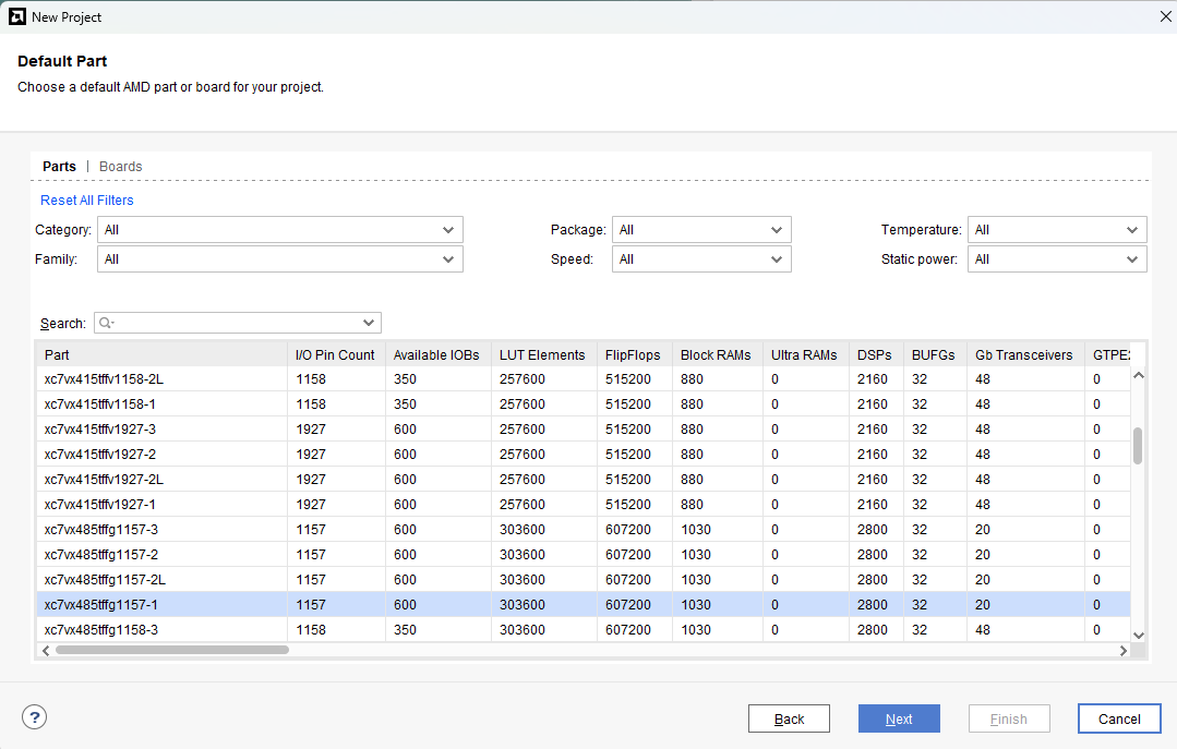
Now we are ready to build a new project. Click "Create Project", click Next on the first window (introductory), give it a name (I used "test_gpio") and location in the next window and hit Next, make sure "RTL Project" is selected in the next window and hit Next, then in the next window "Add Sources" click Next (we won't be adding any) and do the same for the "Add Constraints" window. That brings you to a "Default Part" window:
Click on "Boards" (next to "Parts") and in the search window about halfway down, type "4x2" without the quotes. If you installed the board parts as above, you should see this:
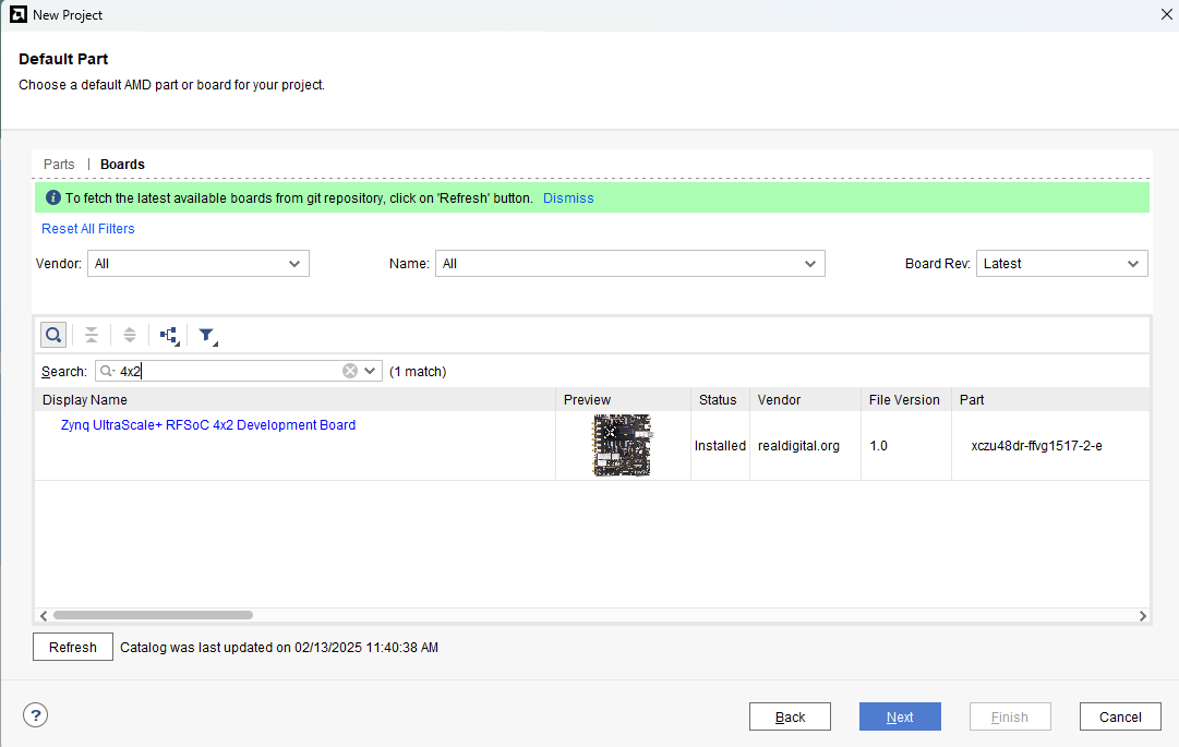
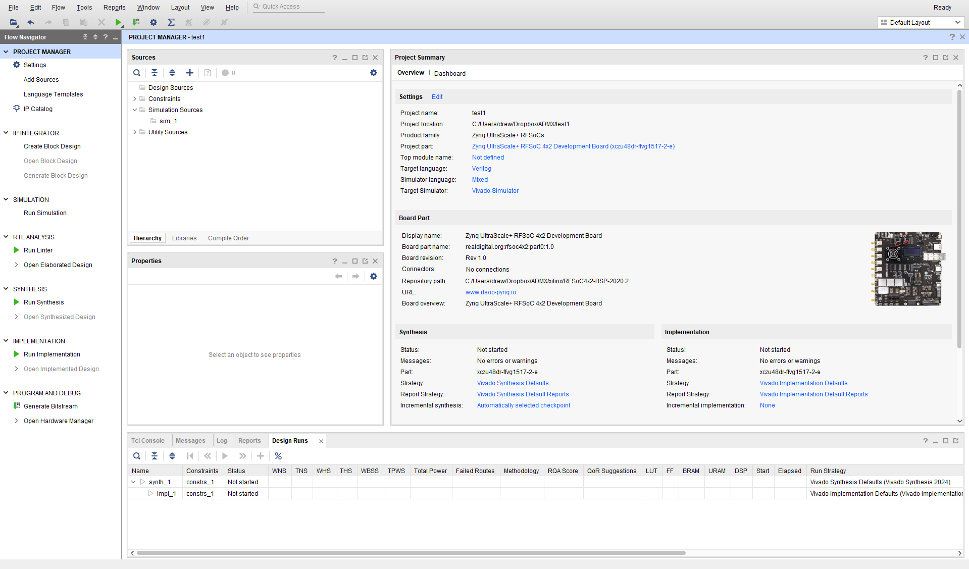
You should see a blue "Zynq UltraScale+ RFSoC 4x2 Development Board" link inside a rectangle. Click on the rectangle but don't click on the blue *4x2* link as it will just send you to a browser that you can close. Then click "Finish" and that will bring you to Vivado's user interface:
Add ZYNQ
The first thing you have to do is set up the project to use the Zynq processor, FPGA, and RF Converter. This starts with the processor, and we will do everything (or mostly everything) by invoking standard Xilinx circuits and connecting them together. So click on "Create Block Design" on the left under "IP Integrator". Give it a name (like "top") in the small pop-up and hit OK. This will show the empty "Diagram" window, and not much else:
Zynq is the "system on chip", and includes 2 ARM processors, FPGA logic, memory controllers and peripherals, and of course the RF converters. So you have to instantiate the Zynq part first. To do that and make it the center of the project, you can click on the bold + menu item under "Diagram", or right click on the diagram and select "Add IP..." or control-I. This brings up a pop-up that has all of the possible IPs, with a search window. Search for ZYNQ, and you should see 2 entries, the one you want is "Zynq UltraScale+ MPSoC". Double click on that and it will show you the ZYNQ block in the diagram window:
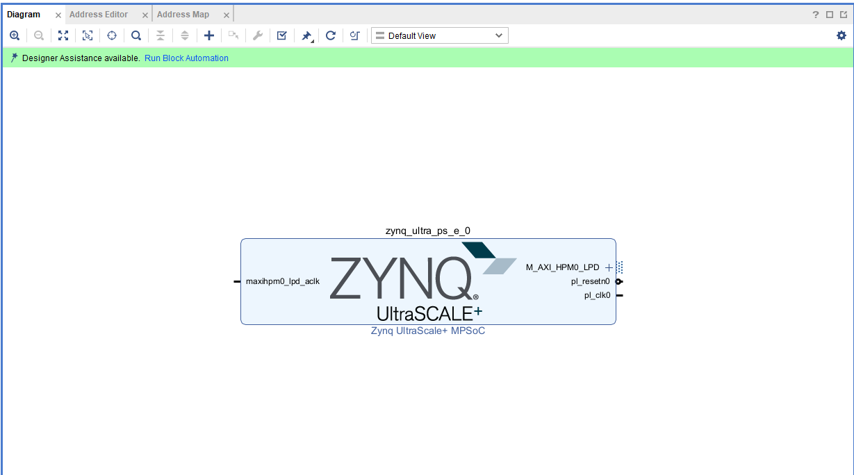
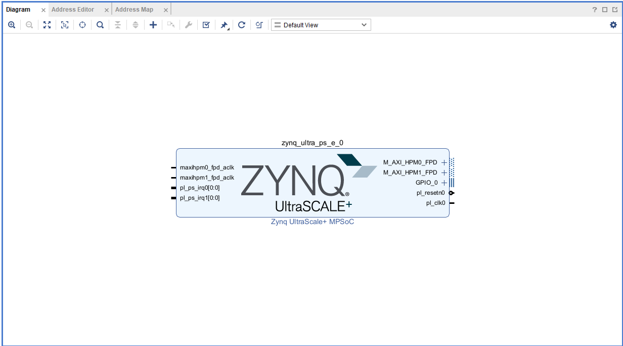
At the top of that window on the left you should see "Run Block Automation". This sets the standard settings to the processor (PS), so click on that, and when it brings up a "Run Block Automation" window, just hit OK. It should now look like this, ready to go (which means it has all the hooks we will need to build a usable project):
AXI bus
The ARM processor will be at the core of everything in these projects, with the FPGA and RF Converters connected on a processor data bus. The protocol for this bus is called AXI, which stands for "Advanced eXtensible Interface". It is a synchronous bus, designed to be able to send bursts of data, with a very simple protocol. AXI is memory mapped into the ARM, so transfering data to various components in the FPGA means all you have to know is the address to read from or write to, and PYNQ takes care of that. The way it does this is that when you build the project, the download file (*.bit) is created, but there is also a *hwh file that is a giant XML file that has all of the addresses that Vivado assigns. When you load the bit file in PYNQ, it also needs the hwh file, and it digs out the addresses from that. You will see more of this below.
The AXI bus is pretty simple: it has a data path (32 or 64 or even 128 bits), a valid line that the master uses to tell the slave that data is valid and can be latched, and a ready line that the slave uses to tell the master that it is ready to receive data. It can be used in full memory-mapped mode (AXI4), a simplified control interface with no burtsts (AXI4-Lite), and a streaming mode to stream data in burst mode (no addresses) called AXI-Stream.
Anyway, the AXI interface is take care of for you by Vivado, so all you have to understand is that it exists, and that you need to invoke instances of the AXI controllers to do any IO on the board.
Add GPIO devices
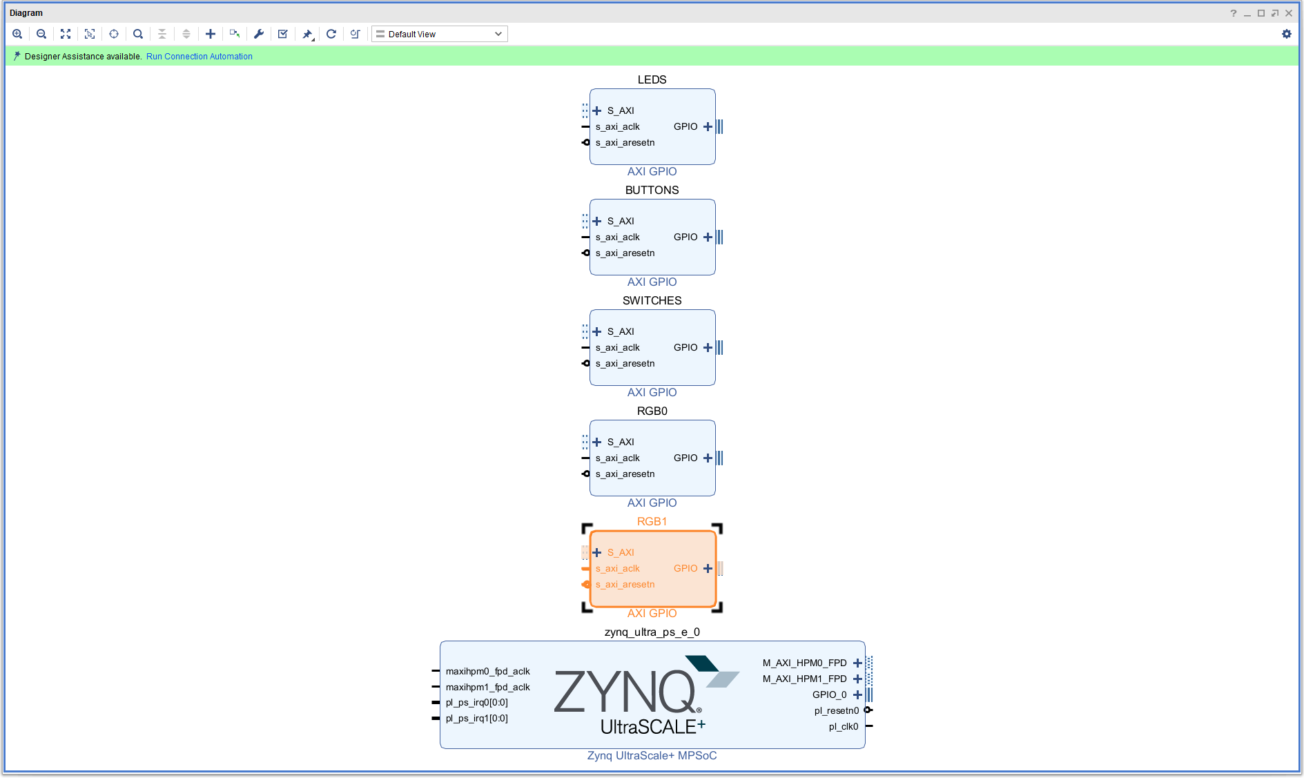
Back to the project. Click the $+$ button to add a new IP, search for "GPIO", and double click on "AXI GPIO". This will instantiate a circuit that will allow you to map an address in the processor (accessible using PYNQ), and connect it to either the LEDS, push buttons, switches, etc. We will need 5 of these for this tutorial, 1 each for the LEDs, push buttons, switches, and the 2 RGB LEDs. You can just copy and past (control-C/control-V) to make 5. It will look like this:
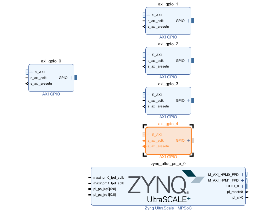
You can rearrange them to make the diagram a bit more symmetric, and this actually might be helpful when looking at the diagram later. You will see a button in the Diagram menu list (it's the row that has a plus and minus button on the left for zooming) that looks like a clockwise circular arrow, if you mouse over it will tell you it's the "Regenerate Layout". Click that button.
Next, we want to name each of the 5 GPIO blocks to be something meaningful and not just arbitrary names like "axi_gpio_0" etc. This will be useful when we get to how to control things in python. To do this, single click on one of the GPIO blocks, and find the "Block Properties" window in Vivado. In that window you can change the name to LEDS and hit return (or click on the diagram window). You should see the block name (which is at the top of the block) change. Do this for the other 4, name them "BUTTONS", "SWITCHES", "RGB0", and "RGB1" in any order.
Now that they are all named according to function, we have to specify that function. You do this by double clicking on each block. Start with LEDS, double click, it opens up a window called "Re-customize IP":
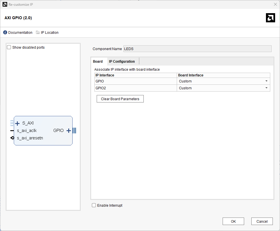
Find where it says "Board Interface", and change the value "Custom" on the row that has GPIO "led 4bits" and hit OK. What's happening here is that Vivado knows this board, so it knows what's on it, and makes it easy for you to use them all!
Make the same changes to "BUTTONS" (change "Custom" to "push buttons 5bits"), "SWITCHES" (change to "dip switches 4bits"), "RGB0" (change to "rgbled0") and "RGB1" (change to "rgbled1"). You should see something like the following:
Now we have to connect all of these GPIO blocks to the Zynq chip over the AXI bus. This is a very complicated process that becomes really easy thanks to Vivado. In the above window, you can see at the top in light green "Designer Assistance Available. Run Connection Automation" with the last 3 in blue. Click on the blue "Run Connection Automation" and Vivado will make sure everything gets connected properly. But first, when you click on it it brings up a new window called "Run Connection Automation", select "All Automation" (top left) of that window, and hit OK. Vivado will magically connect everything together, and even instantiate the output pins. You should see something like this.
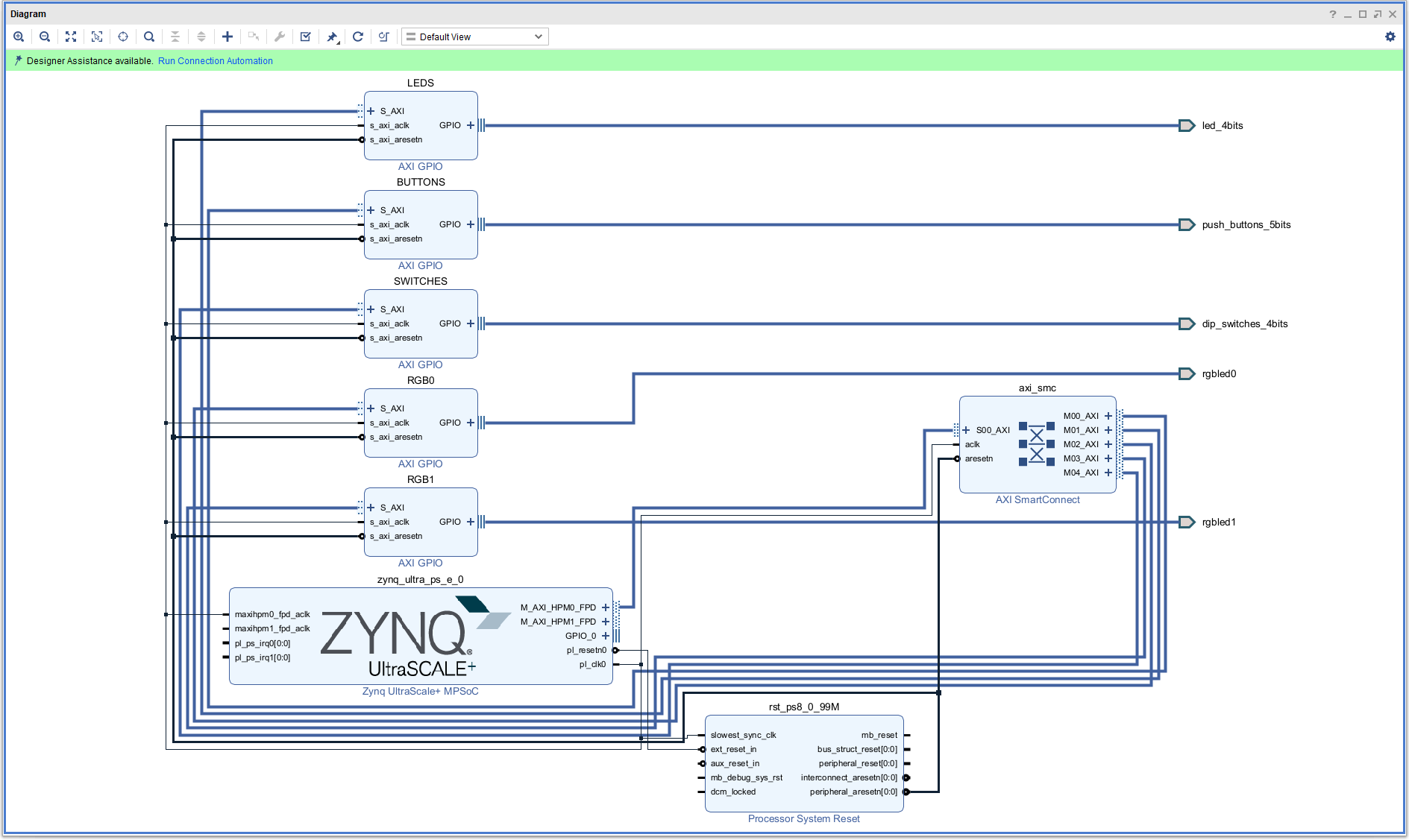
But you might still see the light green banner with another "Run Connection Automation" in blue above. That's because there's still more for Vivado to connect. So click "Run Connection Automation" again, it will bring up a new window and it should have everything selected in that window. So just hit OK. After that auto connection is done, the banner should disappear and you should be good to go with everything connected.
Notice that Vivado added a "Processor System Reset" block to manage reset signals, and an "AXI Interconnect" block that connects all 3 AXI GPI blocks to the Zynq processor (the PS).
Vivado also sets the addresses for the 5 GPIO blocks, so that you can talk to them with python using the PYNQ library. To see these addresses, click on the "Address Editor" in the upper left corner of the Diagram window, and expand everything. You should see this:
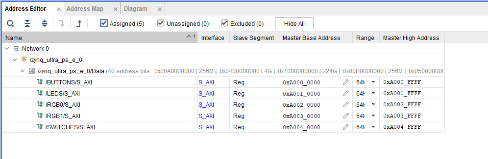
All of the addresses are there, if you need them, but the PYNQ library will make it easy to talk to the 5 GPIO blocks without knowing these addresses.
Top Level wrapper
Next you have to create a top level instantiation of the project. Think of this as the name of the circuit you just created, and all of the IO that needs to be connected. You do this by going into the "Sources" tab (next to "Design", "Signals", and "Board"), right click on the top.bd diagram file, and select "Create HDL Wrapper". That will bring up another pop-up called "Create HDL Wrapper", make sure that "Let Vivado manager wrapper and auto-update" and click ok. When that is done, you will see a new hierarchy in the Sources tab that should look like this:
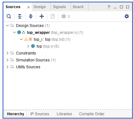
Probably this is a good time to save the design (control-S).
Build the project
Now you are ready to build the project. First, let's do a design validation, which checks basic things like port connections, interface matching, etc. These are things that will be flagged bad by Vivado during the project build stage, but it's faster to find some of them at first. To do validation, hit F6 or select "Validate Design" from the Tools menu, and Vivado will run through everything. (It might pop up a window that says that the validation is already "in the validated state", so you can then cancel the validation.)
Assuming all is well, we can build the project. Let's do all 3 steps: "Synthesis" (list of resources needed and what's connected to what), "Implementation" (figuring out how to set up the Zynq chip to use those resources), and "Generate bitstream" (make the file to download). If you click on "Generate Bitstream" on the lower left, Vivado will recognize that you haven't done the synthesis and implementation and ask you if you want to do them in a pop-up window. Say yes. It will then pop up a "Launch Runs" window, hit "OK".
While Vivado is busy working, you can look at the bottom pane and see tabs "Tcl Console", "Messages", "Log", "Reports", and "Design Runs". Click on "Design Runs" to see where Vivado is in it's stages, and how much time it has taken in those stages. You can also see that Vivado is busy by looking at the upper right corner of Vivado, it should show a circulating icon that means it is busy, and what it's working on. In the "Messages" pane you can see info, warnings, and any errors.
On my Dell EVO, it took about 1 minute for synthesis and 4 minutes for implementation. After the project is done, assuming no errors, it will pop up a "Bitstream Generation Completed" window with "Open Implented Design" selected. If you hit ok it will do a lot of work and show you the actual layout of things on the chip, but that's not necessary to see. Just hit "cancel" instead.
The relevant files you will need are the *.bit file and *.hwh file. Note that the directory structure Vivado creates when you create a project has the following format: let the project name be something like "test_gpio". Then there will be a bunch of subdirectories called "test_gpio.gen" and "test_gpio.runs" etc. The bit file can be found in the "test_gpio.runs/impl_1" directory, and it will have a .bit filetype and will be the only .bit file there. The hwh file can be found in "test_gpio/gen/sources_1/bd/<name>/hw_handoff" and should be the only file there. You will need to copy these files to the 4x2 board in the ARM processor linux filespace.
On my Dell laptop (Intel Core Ultra 7 155H, 32G RAM) it took 1 minute for synthesis and 4.5 minutes for everythign else.
Using PYNQ
Boot up the board and connect to it over whatever link you have set up to open a Jupyter lab. You should see this in the upper left corner of the browser:
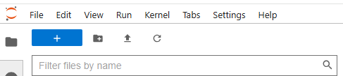
The button 2nd from the right (up arrove with a line below) is the upload button. Click on that and navigate to the project that you just built. Then find the bit file created (see above) and upload it to the board (it's big and will tell you so!), and then navigate to the hwh file and upload that as well. Then rename both files to the same name (I called mine "test_gpio", so I have "test_gpio.bit" and "test_gpio.hwh" files there). Open up a new python notebook and import these:
from pynq import Overlay, MMIO
from pynq.lib import AxiGPIO
Next download the bit file to the Zynq FPGA board by doing this:
base = Overlay("test_gpio.bit")
base is your pointer to this object, and Overlay will take care of downloading the
bit file and parsing the hwh file. If those files don't have the same filename then Overlay
will complain!
Next, let's look at the dictionary by doing this in another cell:
base.ip_dictIt should show you this:
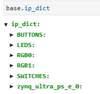
You should see all of the GPIO blocks represented in the dictionary, which means that you can map to them.
Let's first show how to deal with the LEDs. We can extend that to the others.
There are several ways we can write to the LEDs. The easiest is probably to use the AxiGPIO functions built into PYNQ. To use this, you have to set things up by putting this into a notebook cell and executing:
led_ip = base.ip_dict["LEDS"]      # this sets up the pointer to the address dictionary
led_mask = 0xffffffff              # needed to specify what bits to use, 0xffffffff means use them all
leds = AxiGPIO(led_ip).channel1    # there are 2 channels for GPIO but mostly we only use channel 1
There are 4 LEDs, each one mapped to to a bit, so if you write a 0x5 = binary 0101, it will turn on LEDs 0 and 2 (0 is the LED labeled PL_LED0 on the board). So to turn on those LEDs, you do this:
leds.write(5,led_mask)There is another more direct way that avoids using AxiGPIO. That is to use the MMIO function built into PYNQ (it needs to be imported with Overlay, as above). To use MMIO you first do:
led_addr = base.ip_dict["LEDS"]["phys_addr"]         # get the physical address from the dictionary
led_range = base.ip_dict["LEDS"]["addr_range"]       # get the address range from the dictionary
This sets up the pointers to addresses in the dictionary. For fun, you can open up the LEDS entry in the dictionary in the cell where you did "base.ip_dict". You should see this:
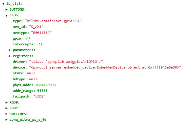
You can see the "phys_addr" and "addr_range" entry, and these will match what's in the "Address Editor" in Vivado. Of course 65535 for "addr_range" is way overkill, and there's probably an easy way to fix this but I'm not sure, and it might be a minimum and anyway there's plenty of address spaces so we can leave it alone.
After defining these dictionary entries, to get the pointer to the memory location mapped to that address you do this:
led_pointer = MMIO(led_addr,led_range).arrayThen led_pointer[0], which is all you need, points to the LEDs. Since the LEDs are just bits in a 4-bit word, you only need the 0th element of that array. So
led_pointer[0] = 5 # turn on LEDs 1 and 3You can also read:
print(led_pointer[0]
To read the 4 slide switches, you do the same thing as above:
switches_ip = base.ip_dict["SWITCHES"]
switches = AxiGPIO(switches_ip).channel1
Then to read the switches, you can do this:
i = switches.read()
print("Switches make a hex word: "+hex(i))
And it will print out the value of the switches as a hex word. For instance, if you have all
switches in the down position, when you execute that cell you will read out a 0. If you set them
all down but the left one up and read it out, you will read out 0x8.
You can also read each switch separately by doing this:
i = switches[0].read()
print(i)
It get the state of the right most switch and print out 0 if down, 1 if up. And so on for the other 3 switches.
Now for the push buttons. There are 5 on the board: 4 at the bottom labeled PL_PB0 to PL_PB1, and these are all active high. Then there is a button above PL_PB3 called URST that is active low. These buttons make a 5-bit word, where URST is the MSB and the other 4 are the lower 4 bits. You can use AxiGPIO to read all 5 and just test on which have been pushed, but remember URST is active low so if it's not pushed, it will return a 1.
To read all 5 without pushing any:
buttons_ip = base.ip_dict["BUTTONS"]
buttons = AxiGPIO(buttons_ip).channel1
i = buttons.read()
print(i)
you should get a 0x10000 = 16 returned because the URST is active low, so it will be high if not pushed.
The last pieces are the RGB LEDs. There are 2 of them, and to get to each one you use the dictionary name "RGB0" and "RGB1". The way these work is that the value for the channel in each GPIO write is used to determine the color: LSB is red, next is green, and MSB is blue. Here is a cell that will turn LED0 to blue:
rgb0_ip = base.ip_dict["RGB0"]
rgb0 = AxiGPIO(rgb0_ip).channel1
mask = 0xffffffff
red = 1
green = 2
blue = 4
rgb0.write(blue,mask)
And the same thing applies to the other RGB LED, "RGB1".
Bit file Compression
The bit file that's created can be quite large (33MBytes) for a file that has to be downloaded. There's a way to make this file compressed, with uncompression happening automatically for you when the file is loaded in. Actually, there are several ways to do this, but here's what I think is the easiest:
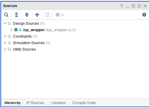
Notice the line ">Constraints(1)". The (1) says that there's a file there, and that's the file you created. Open that line and double click on top.xdc, the new file. It should open the file on the right side of Vivado for you.
set_property BITSTREAM.GENERAL.COMPRESS TRUE [current_design]
set_property BITSTREAM.CONFIG.UNUSEDPIN PULLUP [current_design]
set_property BITSTREAM.CONFIG.OVERTEMPSHUTDOWN ENABLE [current_design]
The first line tells Vivado to compress the bitstream. Since we are making this constraint file, we might as well add the next 2 lines, which just sets a few constraints for safety.
Then save that file, and rebuild the project ("Generate Bitstream") and the new bit file will be compressed from 33MB down to around 10MB, so it should load faster and take up less space on the SD card.