Debugging is a critical part of building a data acquisition system. Fortunately, this is rather easy to do if you can bring out critical signals from the FPGA and look at them with an oscilloscope. But that is somewhat limited by the number of channels on the scope, and in addition, the scope is an analog device so it's somewhat overkill to be able to measure signals that only are at 0 or 3.3 volts (or whatever voltage protocol you are using). What people have done to fill these holes in debugging is to construct a variation on an oscilloscope that will allow looking at way more than just 2 or 4 signals, and apply thresholds to the determine if the signal is a 0 or 1. This is called a "logic analyzer".
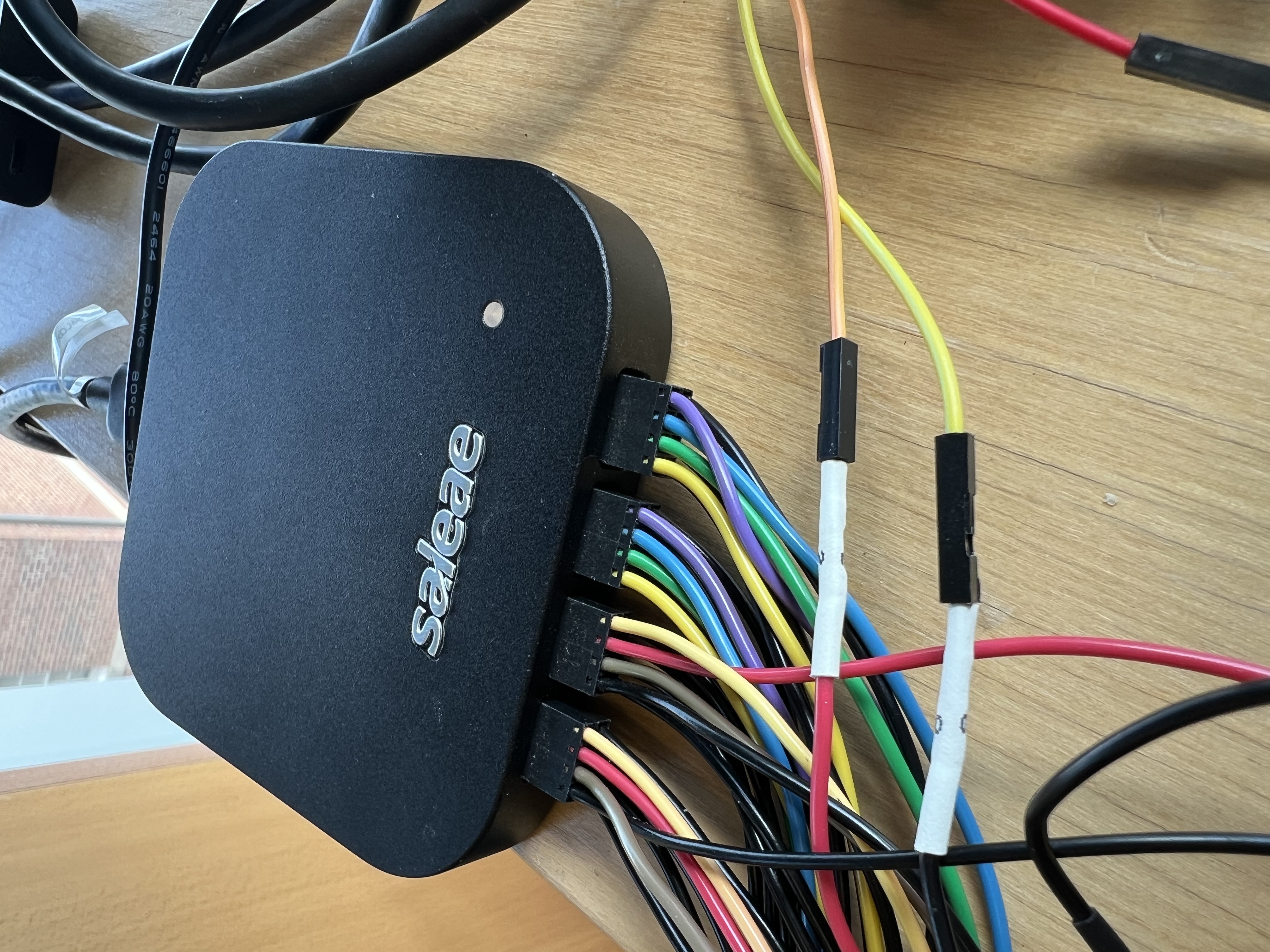
Logic analyzers can cost anywhere between around $1000 up to $100k or more depending on the period of the signal you will be viewing. If like in our case your clock is around 10ns, then you can get a relatively inexpensive logic analyzer that is has many channels, and the one used here is made by a company called Saleae, Inc: the Logic Pro 16:
This gadget has no screen like an oscilloscope, but instead connects to a PC or a MAC over USB. Then you download a program that runs on the computer and makes a display, just like what a scope would do. This makes the hardware pretty inexpensive!
You can see the black square connectors on the front of the Logic Pro 16 that have different colored wires coming out. The connects have 2 rows of 4 wires, the top rows (what you can see) are the signals and the bottom rows are ground wires. These wires terminate in female pin connectors that you can use to connect to signals, and we will use them to connect to the J connectors on the BASYS3 board. Once you set up the program correctly, you can then set the voltage protocol, and the timing, and define a "trigger" condition. The logic analyzer will monitor the signals, apply a voltage to determine whether the signal is 0 (below the threshold) or 1 (above the threshold), and display a waveform pattern.
The Logic Pro 16 has 16 channels (hence the 4 connectors of 4 inputs each), and can show both what's happening on the wire in either analog or digital, but it doesn't have much capability to display more than 4 analog signals at a time. As for digital, it can measure all 16 signals at 12.5MSps (samples per second), 8 at 25MSps, 6 at 50MSps, 3 at 100MSps, or 2 at 125MSps, and 1 at 250MSps. This might seem too slow for our BASYS3 board that has a 100MHz clock (10ns period), because if the logic analyzer can only sample say 4 wires at 50MSps (20ns period), it could miss some of the transitions and you might not see the entire waveform.
Note that for the projects we will be working on here, we will not need a 10ns clock. In fact, the fastest we will need to have the logic change state will be 1MHz, the speed of the ADC. So what we can do is to take the input clock and divide it down and use the slower clock as the system clock to run the logic, and all we have to do is slow it down to something like a 25MSps logic analyzer can keep up with. So if we slow it down by a factor of 8, we would have an 80ns clock and a logic analyzer that runs at 25MSps (40ns sampling), so we are sure to not miss any transitions.
Let's assume that you have some signals you want to monitor, and you bring them out one of the BASYS3 PMOD connectors and route those signals into up to 8 channels of the logic analyzer. Then run the application that you download and install from SALEAE. Assuming that the gadget is plugged into a USB port, the application should automatically detect it, and you might get a warning that you've connected to a USB2 port and so your bandwidth will be limited. If all goes well you should see the following screen:
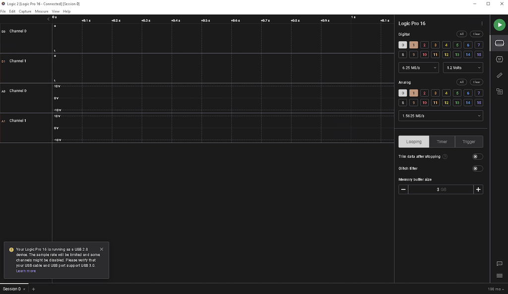
You can see that the default is to enable 2 digial ports (0 and 1 are selected) and 2 analog ports (also 0 and 1). For the time being, we don't need the analog ones so go ahead and deselect those, and select digital ports 2-7 so that the entire row is highlighted. Then, in the drop down that says "6.25MS/s" (just above "Analog"), change that to "25 MS/s" and change the one to the right of it from "1.2 Volts" to "3.3+ Volts", since our FPGA puts out single ended signals that vary between 0 and 3.3 volts. Then below "Analog" where there are 3 boxes that say "Looping", "Timer", and "Trigger", click on "Trigger". This gives you the ability to decide what signal you want the logic analyzer to monitor (which channel, whether you want to show the waveform when that signal goes high or low (posedge or negedge). What the gadget does is to collect data at the rate specified, put it in memory, and when the trigger condition is satisfied, ship it to the computer over USB for display. So you can tell it how big a buffer to use, and how many seconds of data to capture and transmit after and/or before the trigger. For our purposes, you can leave the settings as defaults or play with it as you wish.
Now you are ready to debug!